- Home
- Product Categories
- Motor Accessories
- Wheel Encoder Kit

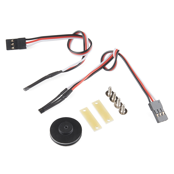
This is the Wheel Encoder Kit from DAGU, a simple add-on to any wheeled robot that can help measure the speed or distance the chassis travels. Each wheel encoder kit consists of two neodymium 8-pole magnets with rubber hubs and two hall-effect sensors terminated with 150mm cables and 3-pin female servo headers. These wheel encoders require a supply voltage of 3-24V with a supply current of 4mA.
- Supply Voltage: 3-24V
- Supply Current: 4mA per sensor
- Output Voltage: 26V Max
- Output Current: 25mA Continuous
Wheel Encoder Kit Product Help and Resources
Experiment Guide for RedBot with Shadow Chassis
May 28, 2015
This Experiment Guide offers nine experiments to get you started with the SparkFun RedBot. This guide is designed for those who are familiar with our SparkFun Inventor's Kit and want to take their robotics knowledge to the next level.
Core Skill: Robotics
This skill concerns mechanical and robotics knowledge. You may need to know how mechanical parts interact, how motors work, or how to use motor drivers and controllers.
Skill Level: Experienced - Your experiences should include working with stepper motors and feedback system. You may need to understand how encoders and more complex control systems work.
See all skill levels
Core Skill: DIY
Whether it's for assembling a kit, hacking an enclosure, or creating your own parts; the DIY skill is all about knowing how to use tools and the techniques associated with them.
Skill Level: Noob - Basic assembly is required. You may need to provide your own basic tools like a screwdriver, hammer or scissors. Power tools or custom parts are not required. Instructions will be included and easy to follow. Sewing may be required, but only with included patterns.
See all skill levels
Core Skill: Electrical Prototyping
If it requires power, you need to know how much, what all the pins do, and how to hook it up. You may need to reference datasheets, schematics, and know the ins and outs of electronics.
Skill Level: Noob - You don't need to reference a datasheet, but you will need to know basic power requirements.
See all skill levels
Comments
Looking for answers to technical questions?
We welcome your comments and suggestions below. However, if you are looking for solutions to technical questions please see our Technical Assistance page.
Customer Reviews
4.5 out of 5
Based on 6 ratings:
2 of 2 found this helpful:
Approximating travel distance
The encoder is working well for me. I've mounted the magnetic disk on the drive shaft of a 4x4 car, after removing the rubber backing. I had first tried mounting the disk on an axle, but I over tightened the wheel nut and broke the disk. It looks like a washer made of steel, but it is more brittle than I expected. It is working well on the drive shaft for counting revolutions, approximating travel distance.
1 of 1 found this helpful:
Easy to setup and use
I was able to install the discs on my existing DAGU motors, no problem. It took a little bit of wrangling and ties to get the Hall Effect sensors in the right place. Then I was able to read the change in state on the encoders using the attachInterrupt() call in Arduino.
1) A pullup resistor on the output line was useful to get clear signals. 2) If you use the CHANGE sense type for attachInterrupt, then you will get all the rising and falling signals (8) and get the most resolution.
https://plus.google.com/+MarkWomack0/posts/X8C7rvfbdUT
1 of 1 found this helpful:
Worked Great!
Bought this kit as a supplement for the RedBot robot kit that you offer. The item(s) worked as needed to get motor feedback to perform more complex tasks.
0 of 1 found this helpful:
Pullup resistor
How do I determine what size of pullup resistor to use?
The short answer - for most applications, anything from 3.3k to 10k is fine.
For the long answer, check here: https://learn.sparkfun.com/tutorials/pull-up-resistors.
Great low-cost encoders!
These are great encoder assemblies. I've used them for a couple of small autonomous robots I've made. The magnetic heads are small enough that they can be placed next to each other, with careful spacing, to create a quadrature encoder to increase resolution and gain direction information.
I've never used any of the provided mounting hardware, but I've found a zip-tie on the shaft of the rotational element I've been trying to measure has been sufficient for enough for reliable mounting. Additionally, the black part attached to the magnetic ring can also be easily removed to allow the encoder to more easily fit over a larger shaft with your own mounting hardware.
Simple and Easy way to introduce encoders
My students are using the hobby motors on their robots and needed a simple way to track the distance their robots have traveled. They were able to easily retrofit their robots with a single encoder and pull in the Redbot library to make this happen. Works well and the SparkFun video that explains encoders helped them understand how the magnetic poles works. We attached our encoders to the gearbox end of the motor to make it easy, but they work on the motor end as well.
What are the yellow strips shown in the picture? Do you have a part number or datasheet on the actual sensors?
I have reason to believe the hall effect sensors are these. The yellow strips are probably adhesives.
They are just mounts for the sensors.
Mounds of what, Rob?
mounds? I clearly said mounts.
The asterisk never lies.
Well, unless I tell it to lie. In that case it might.
Their are just mounds for the censors?
How do I work this?! Example code, anyone?
I have the DGo1D 48:1 motors, but the shaft only sticks out about 1 mm. But according to the Redbot kit, the motors for the same part have a shaft extending about 1 cm (just a guess from the picture). My motors also have a black cap instead of a red one. So I assume my motors are old, so I tried to find new motors and they look totally different (they are right angled). Will these work with RedBot? https://www.sparkfun.com/products/13260
Do you need to use both if you want to tell which direction it's going?
-edit: found the answer. it seems like it should be possible to use two sensors to get the quadrature benefit, but it seems like it's going to be too difficult for me to get them precisely mounted well enough for it to work correctly. I'm also not sure how well that would work with Hall sensors since they detect a spectrum (analog) signal as opposed to the 1/0 of an optical encoder. I'm just going to get the quadrature encoder (COM-10932) to keep myself sane.
Great inexpensive encoder. If you want to use it for a Boe-Bot, here's the longer replacement screw you need for the wheel hub (took me forever to find) http://www.amazon.com/gp/product/B00GDY5C00/ref=oh_aui_detailpage_o00_s00?ie=UTF8&psc=1 it's a #3-24 panhead 1/2" long
When connecting to the RedBot will this connect to the motor shaft (rear of RedBot) or to the gearbox output shaft? Hopefully it's the motor shaft.
Is the RedBot encoder count 48x8=384 ticks / wheel revolution? If so, pretty good upgrade from the current 16 count/rev motor encoder.
Could these be used with servo motors, with the magnetic disc screwed on between the wheels and the servo axle (perhaps with longer screws)?
Accuracy can be thought of as how repeatable is each pulse. Consider the mythical monopole magnet and detect only the rising edge. If you label that as 0 degrees, will it always be 0 degrees, or will the reading wander from 359 to 1 degree? Will it wander from 350 to 10 degrees? How will RPM affect accuracy? I think it would be fun to build a car distributer that will use a knock sensor to advance timing for max engine efficiency under all conditions for a vintage engine. Part of that project would be to know where the crankshaft rotation is to less than a degree. I don't have to measure each degree, I can interpolate if the readings have accurate repeatability.
These work very well with the cheap yellow motors. With some simple code my motors now have lots more torque. http://www.bajdi.com/adding-encoders-to-those-cheap-yellow-motors/
How would this give you Torque?
My guess is that he doesn't talk about the torque of the motor since it is a motor spec, but the torque that is transferred to the ground (i.e. the wheels grip the ground better because of skid detection?). Just a thought.
What is the i/d of the magnet with the rubber hub removed? The motor drive on my robot uses 3/8" shafts. What is the o/d? I also suspect the magnet will pick up all sorts of cr_p from the ground if mounted to close to the ground. Fortunately my motor mounts are 6+" above the base.
How accurate are these? How small an increment of rotation can be detected?
8 poles and 2 encoders should give you 16 counts per revolution. 360/16 is 22.5 degrees per count. With 100 mm wheels (4") that would give you about 2 cm per count. I'd like to know what the output is -- is it totally raw Hall sensors that need conditioning, or is there any clean-up of the signal to turn it into something nice? (Answered my own question: The outputs are open-drain, so all the clean-up needed is a pull-up resistor.)
You can get 32 counts per revolution with this configuration if you can detect rising and falling edges on both channels. Though I don't know if these edges would be equally spaced with this magnetic encoder.
I don't think so. I think the rise/fall is already included in the "poles." 8 poles means 4 magnets. 4 magnets timesd two poles/states each (north and south, high-and-low) times two encoders equals 16 transitions/counts. I could be mis-understanding how the poles are counted, though.
I suspect 1/8 of a revolution based on the 8 poles of the magnet. Edit -- I forgot there were 2 sensors. jwatte is correct!