- Home
- Product Categories
- Arduino Boards
- Pro Micro - 5V/16MHz

Pro Micro - 5V/16MHz
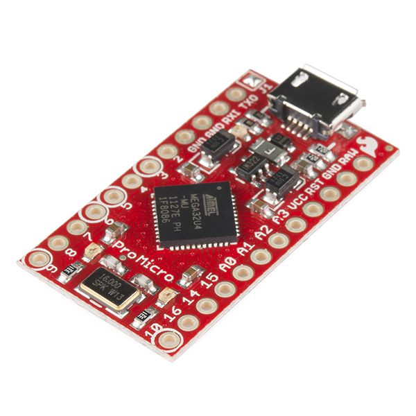
Here at SparkFun, we refuse to leave 'good enough' alone. That's why we're adding to our line-up of Arduino-compatible microcontrollers once more! The Pro Micro is similar to the Pro Mini except with an ATmega32U4 on board. The USB transceiver inside the 32U4 allows us to add USB connectivity on-board and do away with bulky external USB interface.
This tiny little board does all of the neat-o Arduino tricks that you're familiar with: 9 channels of 10-bit ADC, 5 PWM pins, 12 DIOs as well as hardware serial connections Rx and Tx. Running at 16MHz and 5V, this board will remind you a lot of your other favorite Arduino-compatible boards but this little guy can go just about anywhere. There is a voltage regulator on board so it can accept voltage up to 12VDC. If you're supplying unregulated power to the board, be sure to connect to the "RAW" pin on not VCC.
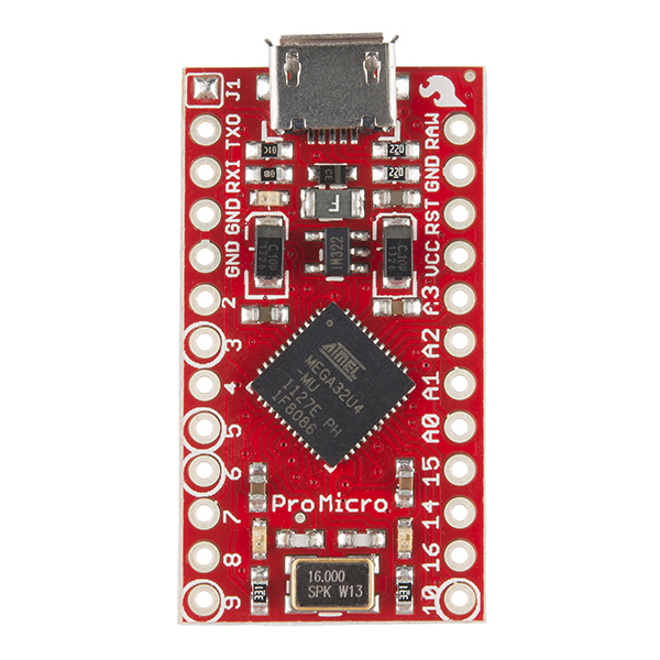
This latest revision corrects the silk error from the last version of the board so that pin 14 is correctly labeled. We've also added a PTC fuse and diode protection to the power circuit and corrected the RX and TX LED circuit.
Not sure which Arduino or Arduino-compatible board is right for you? Check out our Arduino Buying Guide!
- ATmega32U4 running at 5V/16MHz
- Supported under Arduino IDE v1.0.1+
- On-Board micro-USB connector for programming
- 9x 10-bit ADC pins
- 12x Digital I/Os (5 are PWM capable)
- Rx and Tx Hardware Serial Connections
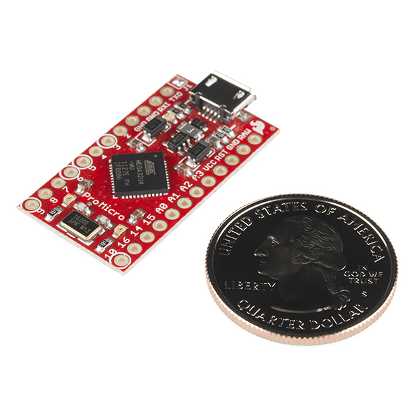
- Our Smallest Arduino-Compatible Board Yet!
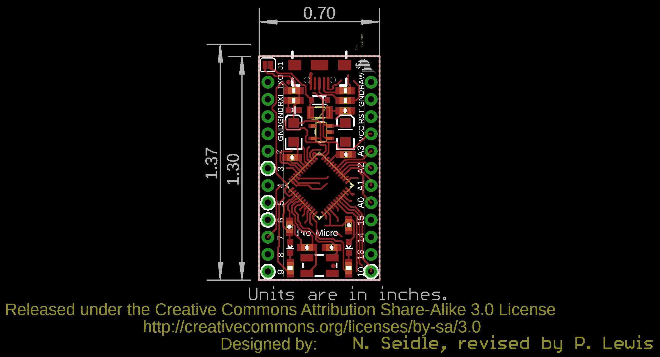
- 1.3"x0.7"
- Schematic
- Eagle Files
- Board Dimensions
- Hookup Guide
- Graphical Datasheet
- Datasheet (ATmega32U4)
- Firmware Note
- Arduino Addon Files
- Arduino Addon Files (IDE 1.5+)
- GitHub (Design Files)
Pro Micro - 5V/16MHz Product Help and Resources
Choosing an Arduino for Your Project
December 11, 2017
Examining the diverse world of Arduino boards and understanding the differences between them before choosing one for a project.
Pro Micro & Fio V3 Hookup Guide
November 8, 2013
An overview of the Atmega32U4-based Pro Micro and FioV3, how to install it, and how to use it with Arduino.
Issues Uploading with Linux
If you have problems uploading code with this error using the Pro Micro on a Linux machine:
 avrdude: ser_recv(): programmer is not responding
 avrdude: butterfly_recv(): programmer is not responding
try following these instructions from Arduino => http://forum.arduino.cc/index.php?topic=217910.0. They need to change some udev rules. There was a customer had the same problem but got it working after changing the settings.
Software Reset
By connecting to the FioV3 at a baud rate of 1200 and closing the COM port, this will initiate a software reset with the Atmega32U4 just like the Arduino Leonardo (as stated in the Automatic (Software) Reset and Bootloader Initiation for a Leonardo => https://www.arduino.cc/en/Main/ArduinoBoardLeonardo ) .
serialEvent() and serialEventRun()
The serialEvent() function is not compatible with the Esplora, Leonardo, or Micro” that uses the Atmega32U4 https://www.arduino.cc/en/Reference/SerialEvent.
There was a customer that was able to resolve this by using the serialEventRun(). For more information, try looking through this forum that helped the customer resolve the issue => https://forum.sparkfun.com/viewtopic.php?f=14&t=41515.
Bricked Atmega32U4
Timing Issues w/ USB Communication through CDC
Interrupts Atmega32u4's built in CDC driver for USB communication can have timing issues when messing with the watchdog timer, sleep modes, and timer interrupts. I am unsure of how to fix this issue if you continue to use code that interferes with the CDC. I recommend trying a different method than using the interrupt timers.
Wrong Bootloader It's possible to brick your Pro Micro 5V/16MHz if you used the wrong board selection with the wrong frequency. If you upload the wrong frequency, the IC will not be able to understand any new code that is being uploaded. It expects to have code that is compiled for another bootloader, instead of using the 16MHz frequency with the oscillator.
When either of these cases happens, the device manager is not able to recognize the device and is usually seen as an "unknown device" when the microcontroller runs the sketch. There are ways to recover the an Atmega32U4 (i.e. LilyPad Arduino USB - Atmega32U4 board, FioV3 - Atmega32U4, Pro Micro 5V/16Mhz, Pro Micro - 3.3V/8Mhz, etc) if this happens. Check below for more information:
A.) Upload when LilyPad USB with Atmega32U4/Pro Micro/FioV3 is still in Bootloader Mode
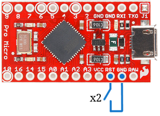
You can try the double reset method by tapping the RST pin to GND twice (since there is no reset button on the board) as explained in the Troubleshooting sections labeled as Reset to Bootloader and How to Revive a "Bricked" Pro Micro => https://learn.sparkfun.com/tutorials/pro-micro--fio-v3-hookup-guide/troubleshooting-and-faq.
1.) Open the Arduino IDE.
2.) Choose a simple code to upload on the Arduino. I used the blink test code from the hookup guide [ https://learn.sparkfun.com/tutorials/pro-micro--fio-v3-hookup-guide#example-1-blinkies ] to upload.
3.) Check your Tools>Port menu for the list of COM ports when the Arduino is connected. You will probably not see it in the list.
4.) Click somewhere else to stop viewing the list of COM ports.
5.) Ground the RST button 2x as stated in the Troubleshooting and FAQ [ https://cdn.sparkfun.com/assets/6/d/3/4/a/523c8e23757b7fbe5f8b4584.png ].
6.) Re-open the Tools>Port menu to view the list of COM ports again to see what the Pro Micro enumerates to when its in its bootloader. There is an 8 second window to view the COM port when the board is in bootloader mode.
Note: Feel free to use the device manager at this step. Opening up the device manager on your operating system will help to see when the Arduino pops up and disappears.
7.) Select the COM port that the Pro Micro is on before it disappears again.
8.) Hit the Upload button to compile and upload.
9.) Wait a few seconds for the Arduino IDE to compile code. The progress bar should be just over the halfway mark.
Note: On Windows, this takes about 20 seconds to compile and upload. The device will show up as "SparkFun Pro Micro (COM##)". Trying this on a Mac seemed a little faster to compile and upload.
10.) Hit the reset button twice again to place the Pro Micro in bootloader mode while the Arduino IDE is uploading.
11.) If successful, you will have no error messages the Arduino IDE will tell you that it is "Done uploading."
After selecting the correct board definition and timing the double reset method correctly, I was able to upload successfully. It took me a couple of tries before I could get this right because of the timing. You should not need to go through this recovery procedure for subsequent uploads unless you brick the Atmega32U4 again.
---------------------------------------------------------------------------------------------------
B.) Outdated or Corrupt drivers
If board is showing up as Arduino Micro (COM##) or Pro Micro (COM##), try the double reset method and updating the drivers while still in bootloader mode:
1.) Use the double reset method while having the device manager open.
2.) When the board entered the bootloader mode, I right-clicked on the Arduino board in the device manager as shown in this screen shot: [ http://puu.sh/iaYYC/d45153914c.png ]
3.) I updated the driver for the board.
4.) Once the update was completed, I compiled and uploaded the code. When the uploading status bar was half-way through, I did double reset again and the problem was fixed.
---------------------------------------------------------------------------------------------------
C.) Reinstalling the Bootloader
As a last result, you can always try to reinstall the bootloader. The tutorial is designed for the Arduino Uno, but it should work for Atmega32U4's bootloaded with Arduino. The idea is the same but the specifics are different. Start by reading the tutorial => https://learn.sparkfun.com/tutorials/installing-an-arduino-bootloader. The first thing you are going to need is an AVR programmer. You can use a standard AVR programmer or any Arduino with the ISP code on it (the standard code will not work with the Leonardo). You will then need to connect it to the target device (i.e. LilyPad Arduino USB, Pro Micro, Fio V3, Makey Makey, or Leonardo) to reflash the bootloader. Don’t worry about the fuse bits or even the avrdude commands (they’re great, if you are installing third party stuff, but this will work just fine).
1.): Get a programmer
This you can do by following the directions in the tutorial.
2): Connect the programmer/Arduino as ISP to the Target Device
You will need to connect to the same pins to your target device (i.e. LilyPad Arduino - USB, Pro Micro, Fio V3, Makey Makey, or Leonardo). On the Leonardo you can connect it just like the Uno. The LilyPad Arduino - USB has small ICSP pins. I managed to solder wires directly to the pins for access. The Pro Micro does not have an ISP header and the pin numbers are different. Check the tutorial for location of the pins on the programmer. Here are the pins for the Pro Micro Board:
ICSP Pins <=> Pro Micro Pin
   GND    <=>      GND
   RST    <=>      RST
   VCC    <=>      VCC
   MISO   <=>      D14
   SCK    <=>      D15
   MOSI   <=>      D16
Note: There is a silkscreen error and D17 is labeled D14 on the Pro Micro.
3.) Program Using Arduino v1.6+ go under Tools and select the correct programmer (if your programmer uses a COM port select that too), and the correct board (LilyPad Arduino - USB, Pro Micro, FioV3, Makey Makey, or Leonardo). Then select Burn Bootloader. For the Pro Micro, this will use the bootloader in the addon file, so make sure you have the correct addon file installed. You can find the latest board definitions from the SparkFun GitHub Repository [ https://github.com/sparkfun/Arduino_Boards ].
Core Skill: Soldering
This skill defines how difficult the soldering is on a particular product. It might be a couple simple solder joints, or require special reflow tools.
Skill Level: Rookie - The number of pins increases, and you will have to determine polarity of components and some of the components might be a bit trickier or close together. You might need solder wick or flux.
See all skill levels
Core Skill: Programming
If a board needs code or communicates somehow, you're going to need to know how to program or interface with it. The programming skill is all about communication and code.
Skill Level: Rookie - You will need a better fundamental understand of what code is, and how it works. You will be using beginner-level software and development tools like Arduino. You will be dealing directly with code, but numerous examples and libraries are available. Sensors or shields will communicate with serial or TTL.
See all skill levels
Core Skill: Electrical Prototyping
If it requires power, you need to know how much, what all the pins do, and how to hook it up. You may need to reference datasheets, schematics, and know the ins and outs of electronics.
Skill Level: Competent - You will be required to reference a datasheet or schematic to know how to use a component. Your knowledge of a datasheet will only require basic features like power requirements, pinouts, or communications type. Also, you may need a power supply that?s greater than 12V or more than 1A worth of current.
See all skill levels
Comments
Looking for answers to technical questions?
We welcome your comments and suggestions below. However, if you are looking for solutions to technical questions please see our Technical Assistance page.
Customer Reviews
4.3 out of 5
Based on 81 ratings:
1 of 1 found this helpful:
Powerful and great price but...
The surface mount USB connector broke off. If there were through holes adjacent to the connector, I could run a wire over the top for better support.
4 of 4 found this helpful:
nice little alternative to larger arduino boards; but be careful...
I'm using this and the 3.3V version (in separate boxes) to control a few sensors (some of which are 5V, others are 3.3V). They both work just fine; however, be careful when programming to have BOTH the board and processor set correctly under the Arduino Tools menu. My very first use of one of these was with the wrong processor (I had a 3.3V pro-micro, but tools->processor was set to 5V); and the board was bricked after programming.
Admittedly, it was my bad, but it would be nice if Arduino and the bootloader could handshake to verify that the correct settings were used and at least post a warning to the user.
You're right, care definitely needs to be taken to make sure that both Board and Processor are set correctly. There are ways to un-brick the unit, though they can take some time and effort. Take a look at the comments from one of our techs, here: https://www.sparkfun.com/products/12640#comment-55dde917757b7f86028b4567. Happy Hacking!
2 of 2 found this helpful:
Not a fan
I had a great deal of difficulty getting a sketch uploaded. The tweaking you have to do to the IDE is pretty straight forward and well documented (thanks Sparkfun!) but I kept having issues with the bootloader and being able to upload my sketch. I ended up not using the Micro because it was too frustrating to work with when I have other things to troubleshoot. Ended up using a Nano from one of my other projects.
2 of 2 found this helpful:
Fragile usb connector
It did the job until the USB port came off the board. It didn't take much pressure at all, I just barely caught the cord on something at the wrong angle, and it popped right off. I ordered another, and this time I'll be potting the whole thing in epoxy after I solder on the headers.
As a side note, does anyone know if I can cut up a USB cord, solder the data lines to the RX/TX pins, and switch my program to using serial1? This seems like an easier repair than trying to patch into the 220 ohm SMD resistors near the broken USB port.
Edit: I bumped it up by 1 star after some reconsideration. I ended up patching into the 220 resistors on my broken one. Just be aware that if you are going to be using this in a long term situation, you should either (carefully) pot the usb connector in epoxy, or use a housing of some kind that provides support to the connector.
Hello!
Sorry about the issues with the USB port on the board. Have you contacted our technical support team at techsupport@sparkfun.com - they're usually pretty good at helping out with questions like this.
3 of 4 found this helpful:
Excellent product
I am a retired engineer and have been out of the software business for almost 10 years. I purchased the Pro Micro after reading up on the Arduino products and capabilities. I have been playing with the Pro Micro for about a week and have two projects well along in the design cycle. I really appreciate how easy it is to prototype with the Pro Micro and it has some very nice features. The Arduino IDE is a very nice way to develop software too! Sparkfun has some excellent documentation and examples. This has really helped the process of getting back into programming. Thank you Sparkfun!
2 of 3 found this helpful:
ok
all boards like these need better set up software
1 of 2 found this helpful:
Disappointing
I never figured out how to make it work with the Arduino IDE. Don't know why. I gave up and used a ProMini instead.
Be sure to follow along in the Hookup Guide. There is an explanation of how to install on Windows, Mac and Linux. This board does require some extra steps compared to the Pro Mini. https://learn.sparkfun.com/tutorials/pro-micro--fio-v3-hookup-guide#installing-windows Happy hacking
1 of 2 found this helpful:
Fit the bill perfectly
I needed something small with USB onboard to control a strip of NeoPixels.
My project uses a small C# program to communicate over serial with the Arduino which drives the pixels. I wanted something small and this was the only Arduino I could find to fit the bill. The trinket doesn't have serial and the pro mini would tie up my programmer.
That being said, I have had some issues with this showing up in the device manager and for that reason I don't think I would have this as my only arduino. I think your best bet would be to prototype with something like a RedBoard and port your over to this little guy. If I have another project that needs serial communication or USB power I would definitely use one of these. Otherwise I would probably go with a Pro Mini if I needed a small dedicated arduino to stick in a project.
1 of 2 found this helpful:
Great board
love the onboard USB. Only drawback is no onboard reset button. Documentation on this product as far as startup drivers etc is easily accessible. Overall great product
1 of 2 found this helpful:
Not Really Hacker Friendly
If you are thinking of buying this board, get a Pro Mini and the FTDI board instead. The Pro Mini is half the price, and the FTDI board can be reused.
The Pro Micro is too finicky. At some point you will mess up a setting in the Arduino IDE. With many other boards that's not a problem and can be easily fixed. Not so with the Pro Micro. The bootloader is configured to get out of the way quickly, and if you program the board incorrectly, you must perform magic tricks to get the board back to life.
I played with mine for about 20 minutes, and for some reason the Arduino IDE decided to change to the 3.3v version of the board; I swear I did not change anything myself. Programming the 5v board using the configuration for the 3.3v version bricks the board. Sparkfun's website describes the magic tricks you must perform, but after 20 minutes I said the heck with it.
I tossed it in the trash and ordered a Pro Mini instead. If you have a lot of patience or $19.95 is a lot of money for you, you might spend more time getting your bricked Pro Micro back to life. I'd rather spend my time doing something else.
0 of 1 found this helpful:
Very Good Product!
The Pro Micro - 5V/16MHz is a very compact, low-cost, and very effective product.
Great microcontroller for smaller projects that still need usb serial
Just needed it to be a simple LED controller for my computer and it has been nothing but wonderful!
0 of 1 found this helpful:
Best thing I've ever owned!
Allowed me to program a start button for my car!
0 of 1 found this helpful:
Best clone for small projects
Micro usb is a huge plus for powering projects with rechargeable cell phone power supplies. Built in ftdi to serial interface means you can power and configure with one standard cable. I only use SparkFun's arduino clones for this reason.
0 of 1 found this helpful:
Just fine no problems yet.
Great great!
Works great! Additionally SparkFun support is top notch when I had a slight issue.
works fine
Only had a little trouble connecting it to my laptop. Had to reset it twice, then upload a sketch within 8 seconds to connect it to my laptop. When I had that figured out, everything worked without problems.
Solid, small, economical, onboard USB
It's "solid" in terms of reliability, small, economical, and with onboard USB. This has really become my goto board for projects that move from the bench to a permanent installation on equipment where I don't need a huge number of I/O lines or program space.
I like the Pro Micro
I prototyped with the Red Board Arduino and Proto Shield. I fabricate my device with the Pro Micro. I liked the smaller size. The code was of course the same and performance was the same.
well done SparkFun
USB + Arduino in compact size this is the best.
Works out great for 80% of what I need
I use these little arduino boards for all kinds of stuff...drag racing transmission controllers to led sign controllers to frequency agile signal generators. The small footprint and on-board USB make it a breeze to use for rapid prototyping.
Great little micro for home projects!
I've been helping my teenage daughter last few weeks putting together a school project for automated indoor pot plant watering, using a sparkfun soil moisture detector. Getting power consumption down as low as possible has been a challenge, but we have had reasonable success. We drive it off a small garden light solar cell and one AA rechargeable battery via a Pololu boost regulator. I took off the power LED resistor and bypass the input regulator; with the Pro Micro asleep and the boost regulator shut down it consumes very little current. (The official safe operating area at 16MHz is down to 4.5V, but I found it works fine down to 4V).
A number of gotchas which took some time to figure out... 1. Nearly always have to load sketches via the double reset technique to use the bootloader mode; it is a challenge to get the upload timing right since the bootloader mode only gives you an 8 second window. 2. The Arduino digitalPinToInterrupt(pin) function does not map to the correct interrupt number using the pin number as printed on the silkscreen; I had to go by the sparkfun documentation instead.
Prepare to frustration racing the 8 second window
Just started using this board and was happy to get successfully through all the driver loops and uploading the first sketch.
Was ready to move a project from a larger prototype board to this little guy.
Only if I knew that loading a second sketch will be close to impossible...
So while running, arduino can't talk to this board, you need to double short the reset pin, and you get 8 seconds to load a new sketch before the current one starts running. Who made that poor choice? really 8 seconds?
Precision Tone frequencies and 5 V I/O
The Pro Micro 5V/16 MHz board has been my favorite for a long time. My hobby of electroherbalism needs specialized experimental instruments, and this module is the only one that works for most of my projects. For my current instrument design and build, some essential qualities are the precision tone frequencies - accurate to 1 Hz at least to 5,000 Hz - as compared to an Arduino Uno which produces, for example, 529 Hz when a frequency of 528 Hz is specified in tone, quite unusable. And the 5 V interface is perfect for matching with the low cost "LCD Key" common interface which provides both LCD and adequate pushbuttons for my instrument's human interface control. And the Arduino ProtoBoard works nicely for a place to do the pin swap wiring for the Uno footprint the LCD Key needs.
It works, finally
Took a while to download my program, kind of frustrating but eventually I got my timing right.
It does do what I programmed it to do - using it with a ZX gesture sensor to act as a mini-keyboard-like input to a Rpi for a magic mirror project.
I would buy this again.
Frustrating due to poor boot loader!
I use a the Macbook Pro with OS X. Was major pain getting the drivers set up so I could download a sketch. SparkFun warns that the USB can be difficult. I almost gave up. Still cannot get Serial Port Com to operate. USB is finally working enough for my needs. But board is amazingly small and fits in my small enclosure with a OLED. Needs more debugging on the boot loader to be 100% easy to use. I would not have used the product had I known the boot loader would be so much trouble. Come on Sparkfun, put a few more debug hours in!
A lot of function in a tiny package.
Now that I have it up and running, this has been a little champ. Initially, though, it took a bit to get there. First I had to figure out where to get the board package from and how to install it in the Arduino IDE. It's really not that hard to do but without decent directions, I had to fumble my way through. Then, I "soft-bricked" the board by building and uploading with the 3V/8MHz fuse settings. Ooops! My bad! Fortunately, it wasn't hard to find instructions on how to unbrick it. Apparently, this mistake is a common one. But with those "preliminaries" out of the way, it's been working well. If you need an Arduino in a tight package, this product is worth your consideration.
Handy little thing
No stranger to Arduinos, so knew what I was in for - works great for my project and am very satisfied. The ability to upload sketches by USB without the external stuff is great, and the voltage regulator seems to be able to handle what I'm sure is abuse on my part (long story).
The /only/ hiccup was getting connected the first time. I'm a Linux user (Ubuntu), and followed the setup tutorials provided on the SparkFun website, but couldn't figure out why I couldn't upload a sketch. Eventually found that I needed to add the following to my udev config:
ATTRS{idVendor}=="1b4f", ATTRS{idProduct}=="9205", ENV{ID_MM_DEVICE_IGNORE}="1" ATTRS{idVendor}=="1b4f", ATTRS{idProduct}=="9206", ENV{ID_MM_DEVICE_IGNORE}="1"
(a new file within /etc/udev/rules.d/ in my case)
bad so far
I thought I could just use software I'd been using with the mini pro! Now I am wiser but will likely put the board in the bin!
Eben
Hello!
Sorry to hear about the issues with the pro micro. Have you contacted our technical support department @ techsupport@sparkfun.com ? They might be able to help you get your setup working if you're having issues.
Great little arduino for more than prototypes
We are building a little robot and this little guy exceeded our expectatives. I was able to hook it up with the Dual Motor Driver (TB6612FNG) breakout and control DC motors, but we ended controlling 1 servo and 2 continous rotating "servos" and we didn't had any issue.
Worst board ever
I changed my review to 2 stars because it does what I purchased it for. However, I had to read through pages of info before I find out the pin mislabeling and the bootloader issues. That should be #1 on the hookup guide.
Awesome! Great size, features, and price
This is an awesome little board for embedding in projects. Having USB separate from it's UART means that I can upload new code without having to disconnect anything that I have attached to the serial tx/rx pins. Just remember to use Serial1 when you want to talk on the tx/rx pins rather than on USB.
I like to develop and real-world test with this board, and then use the even less expensive Pro Mini when I have my code done and need to make more devices. For anything that might need code adjustments, or computer interfacing, I use this board with it's easy micro USB port.
Hard to get program
I can't seem to get a program loaded on it It won't show up on my ports no matter what I do
Hello!
Sorry to hear about the issues with the pro micro. Have you contacted our technical support team @ techsupport@sparkfun.com - they're usually really good about helping to get these device working.
Love this board.
Very small and has all of the functionality that I need.
Super small and awesome
This board is incredibly small and light weight. Works perfectly with Arduino IDE. You will need a micro USB cable to work with this board, not included.
Good Little Board
Very handy for adding a little intelligence to a bread-boarded circuit. I keep several around at all times.
Nope... Trouble
Was a pain in the butt to finally get working... Had to "reset" several time... then the computer and the chip FINALLY made peace. So far so good but the initial issues made me think I would have to trash the whole thing. WAY too much hassle... Next project will not include this device... I'd rather use a nano than have to go through the pains of reset and problems I faced. Pro Micro... you are dead to me!
Works great as a USB HID
I bought this to act as a special purpose USB HID where it could type and move the mouse for me. The 'double reset' in the bootloader let me easily recover a mistake made in the code by giving me an 8 second window for loading new code rather than 0.75 seconds.
Pro Micro is Great for Embedded Controllers
The 2017 version of the Pro Micro is more-or-less a minimalist implementation of a Leonardo, and is suitable for use as an embedded controller in applications where retaining the potential to support USB connectivity (e.g. to upgrade firmware in the future) is desirable. If I could change anything about it, I would include a simple option to disable the PWR LED to reduce the current draw when operating from an external (battery) source.
I had no issues getting it to work with the Arduino 1.8.3 IDE , but you really do have to carefully follow Sparkfun's boot loader instructions which are a wee bit different for this machine. This is especially true if you accidentally configured the IDE for a 3.3V chipset and you actually have a 5V model (you'll have to follow the de-bricking instructions).
Happy
I've been tempted by Arduino before but this is my first purchase. I bought this to automate some repetitive tasks that I perform at work, and half expected it to sit in a drawer, but was surprised at how quickly I was able to emulate a keyboard and mouse. In about thirty minutes I had a working prototype.
Unpleasant Surprise
I bought the "Micro" by mistake. I thought I was buying (my fourth) "Mini."
I tried to modify my (working, and non-trivial) Mini code to fit the Micro, but ended up just bricking the Micro. Not a big deal, I was able to recover the bootloader; but overall, it was a negative experience.
In the end, the Micro did not have the resources for my project. So I put it on a shelf and ordered another Mini. Maybe I'll find a use for the Micro in the future.
Terrific for getting up and running quickly on a small project
This board is great because it is relatively inexpensive, has plenty of I/O for small projects and comes in two voltage flavors, making it easy to integrate into any existing design. Just be sure to get the instructions on how to obtain the libraries for the Arduino IDE. They can be found in the Hookup Guide in the Documents section.
Best little postage stamp micro for a multitude of projects!...
This little guys packs a serious punch, I've used the Pro Micro's for many projects already, from controlling LED's, motors, GPS receivers, data loggers, keyboard emulators. You can't beat the postage stamp size with USB connectivity and easy to solder header pinout. You just gotta love the Pro Micro, and comes in 5V and 3V flavors as well. I'll be ordering another bunch of them soon.
Great little prototyping board.
SPI, I2C, lots of pins, 16Mhz, program in C, easy to load code via USB. As I said, great prototyping board on your way to a custom PCB board.
one of the most useful small machines around!
The Pro Micro is one of the most useful small machines around. Fits in at any place where control functionality is needed; in-system-programming (reprogramming, repair) is easy via the USB interface and the Arduino IDE (the mobile phone charger cable is always at hand at every place...) ; yet allows to deploy the full power of the RISC chip via C++ and inline ASM, controlling the execution timing down to the level of the machine cycle, providing interrupts for time-critical routines, and also providing a lot of serial communication options for connecting sensors and for transferring data between units and/or peripherals.
Expectations
Neat little creature, works just fine:-)
Works as expected
After installing the correct drivers for the computer and for the Arduino IDE, the board works as expected. I did get into a weird situation where I could not program the board. I was forced to use "double tap reset" to program in a simple program before it behaved properly when programming the board. Not sure what happened there, but the backdoor method worked. This does simplify designs where you want a small Arduino with coms to the outside world and not have to deal with FTDI serial cables and the like.
Fried it
Flashed some code and within 2 min it was fried. Probably my fault, set it down on a cluttered desk. I definitely set a personal record for frying an Arduino.
Perfect for permanent applications
For prototyping and learning, a full size board and breadboard are the way to go. When you're ready to lock in your design, this Pro Micro can't be beat. It's tiny and easy to use, yet has plenty of I/O and can be powered by almost anything, including the USB. A bit difficult to set up in Arduino Studio since it's a clone, but after that you're in the clear. Will buy again.
works great
It works great and is very compact. The only thing I wish it had were some holes for mounting it to a chassis.
Tough choice between this and the Pro Mini
Sometimes it's a tough choice between this and the Pro Mini. If you would just add pads for I2C pullups, and a reset button if there's room, it would be better than the Mini. Otherwise it's a great product.
My favorite little AVR based 5V Arduino
I like the Arduino Uno and SF RedBoard. But once my project is out of the very early stages of prototyping, I need something smaller. I've used these in a couple projects.
It is a bit more expensive than some even more stripped down offerings. However, it includes the programmer and a USB port on the board! That is really convenient. For me that is convenience is super important. I have limited time to spend on my many electronics projects, and having the programmer ready to go is a major time saver.
One comment though: You need to install this into your board manager in your Arduino IDE. And WARNING WARNING WARNING: Make sure that you set the board to the 5V/16 MHz version if that is the board you are using. I bricked one of these because I overlooked this step once. But for me, that isn't a show stopper.
Bottom line: if you are looking for a substitute to you Arduino Uno or SF RedBoard, give this a look.
It is a Joystick
Have you ever wanted to build your own VR tools? I needed a device that I could install in a headset to read sensors and track the position and orientation of my goggles. This little device has that capability and also connects to your PC as a Human Interface Device, allowing me to place sensors in the helmet and send the results back as joystick axes and button presses.
Worked for my project
A Power Wheels conversion. Braking resistors, a relay, 24v battery, 500W brushed DC motor controller with thumb throttle. Programming basically went like make some variables for relay position, 5v in from thumb throttle reading, 5v out for motor controller, loop went, if throttle is above a threshold, flip relay on, like read throttle, if that number is higher, wait 10ms, increment by one, if lower wait 10ms de-increment by 3, if below threshold, de-energize motor, wait 10ms, flip relay off (braking resistors slow the power wheels).
I got it working, project complete and I am happy with it. Goes a good jogging speed now.
I did have an issue with the USB becoming detached from the board. I wanted to change the code some more, but I will likely need to do some very fine soldering and just use wires soldered to the board.
Great, but don't upload to it until you select the right version
When uploading to the board, make sure the correct version (5v vs 3v) is selected. otherwise you will brick the board, and the only solutions are to buy another OR go through a frustrating reset process.
Works where cheaper ones don't
I am using this board strictly for a USB interface. So far it has not failed. I tried several of the cheaper boards and they either failed within a few days or didn't work at all. Time will tell with the ones from sparkfun.
Works where cheaper ones don't
I am using this board strictly for a USB interface. So far it has not failed. I tried several of the cheaper boards and they either failed within a few days or didn't work at all. Time will tell with the ones from sparkfun.
Just the ticket!
I was looking for a small form factor solution for a keyboard emulator which would help me by supplying log-in information and access codes I am having to type over and over dozens of times a day. This unit combined with the SparkFun Infrared Control Kit, allows me to quickly enter the information with one button. Since the codes are tied to buttons on the remote, as long as I take the remote with me when I go get coffee, I don't worry about anyone using the ProMicro for bad intentions.
Very Versatile!
This little board is great. I used it to create a custom joystick controller, and it worked perfectly. I honestly should have used a larger board, since I ran out of usable pins, however even with the limited IO compared to larger boards, you can do a lot with this!
Awesome little board
I had one before and broke the USB off. This time I know to be careful and only touch it to plug in the USB cable. I had no problems getting my code loaded. I'm running a chromebook and the Arduino IDE works fine on it. When loading code, it shows up in the USB manager as a Pro Micro 5V, then the code loads and when done loading, it shows as a Leonardo. I've tried several sketches and no problems loading. Right now I am using the I2C to read data from a BNO055 with a BMP pressure sensor. My only concern is maybe I should run this sensor on 3.3V, so I'll probably be buying the 3.3V Pro Micro.
Their nice, but I am having trouble with them .
I own several of them, they are a great small platform for small projects. Have used several of them in various projects with great results.
But lately they lock up and will not accept the USB. The last batch of them I ordered locked up first rattle out of the box. This happened with 3 different computers and 4 different USB cables.... Locked up 3 of the ones I had on hand, and 4 of the 6 I ordered. I tried the trouble shooting guide method to no avail. Had to go to a Arduino Micro just to finish the bread boarded project, so I can design a PCB based on the final circuit design. Would love to use a Pro Micro, but cant get them to work. May have to go with a Arduino Nano for a final build. Will return the locked ones when I have the time to pack them up and get to the PO.
Thanks Clinton Stafford
Great features in a tiny package
These little boards have done everything I have needed them to and are packed with features. Best thing is they are so small you can hide them anywhere!
Just what I wanted.
Extremely small and still had all the power I could ever need for my project.
Great product!
This does everything I need it to in a small form factor. The only issue I have with it is that the USB port wiggles a lot on the board and I'm afraid it will come off at some point. In my current project, I only use the USB to program it.
Awesome little board!
I was building an interface for a project and had used an Arduino Mega for the prototype. I decided I wanted something considerably smaller for the final project and this fit the bill. A couple pin remapping in code and I had this thing up and running in minutes. It works great!
Good thing
Nice quality, thanks
0 of 1 found this helpful:
Hardware is fine, but compiled code is big
If I compile code for the Arduino Uno, it compiles to 5.1kB. If I simply switch the device to SparkFun Pro Micro 5V/16MHz, it bulks up to 8.8kB. Any explanation?
Sorry for the delay in the answer - but the larger compilation size is due to the bootloader for this board (it differs from the Uno).
Small, efficient and extremely flexible package with connection limitations.
Using these small boards in an embedded data acquisition system. The one main bugbear is the USB connector, which we use for data upload and parameter setting on the board. If the board is fitted inside a casing, getting the USB connection externally is at times frustrating. We can't always have the USB connector poking out the side of the enclosure and fitting an extension cable is cumbersome in small cases. It would be useful if a version is offered with a 6 pin header connection for connection to an extension cable, 6-pin to USB-Micro
Cool little piece of tech
Purchased this to handle head tracking for a graduate project, worked out great.
Works great
I love the small form factor and native USB support.
Incredibly powerful and versatile for its size and price
There are many different Arduino platforms out there, some better suited than others for specific projects, but I've never found one as versatile as this little bugger. USB HID support is one of its biggest advantages, but it's small size make it perfect for prototyping compact solutions. Only issue I had was a self inflicted problem where I flashed with the wrong board voltage/frequency selected, causing the bootloader to flake out, but a reset using the Sparkfun directions got me all sorted out.
I have been using this board for some years now, various projects from logging/monitoring to replacement washing-machine controller. I was using it with an older Arduino IDE (1.6.3) and older board defs for all that time, with no trouble (except the delay caused by ModemManager - ubuntu 14.04). After updating OS and IDE to the newer version with the boards-manager in it, the newer board defs define the board as ProMicro with the difference between 5V,16Mhz and 3.3V,8Mhz being on a separate menu, with a default of 3.3V. This makes it WAY TOO EASY to write the wrong settings to the promicro, would be much harder to get wrong if they were still separate boards rather than defined as different processors. Needless to say, I bricked the Promicro when I wrote a 3.3V program to a 5V board. Or did I?
starting upload from the ISP before plugging the board just complained that there wasn't a port there, pressing it as I plugged in took too long before starting the upload and the port was already gone.
I noticed that it still would flash TX and RX LED's for half a second when plugged in, and then noticed that /dev/ttyACM0 appeared briefly too, so the 5V bootloader was there for a moment before the 3.3V program messed up the clocks. I was thinking to try something USB before going the SPI ISP route.
so I found the avrdude bin in the arduino program folder, built the blink example and found the .hex file in /tmp, made a one-line script with an avrdude command to write blink.hex to /dev/ttyACM0 and hovered over the enter key as I plugged in the promicro. I got the timing just right and the led started to blink :)
the avrdude command: $ sudo /home/jeremy/arduino/arduino-1.8.9-linux64/arduino-1.8.9/hardware/tools/avr/bin/avrdude -C /home/jeremy/arduino/arduino-1.8.9-linux64/arduino-1.8.9/hardware/tools/avr/etc/avrdude.conf -v -patmega32u4 -cavr109 -P /dev/ttyACM0 -b 57600 -D -U flash:w:/home/jeremy/arduino/arduino_build_546872/Blink.ino.hex:i
obviously you'd need to change the paths to whatever they are on your system.
I continued to experiment, and discovered that this only works for very small programs. even avrdude on its own takes too long between checking the port exists and starting to upload if the program code is longer (blink worked at 4128 bytes, the code I actually wanted was more like 22k and that didn't work with avrdude in the command line. The ISP does a different upload sequence which stops the normal code running, so it can take longer and works, most of the time, though sometimes I get a 'permission denied' error that goes away if I try again after 20 seconds.
In short, the newer IDE seems less well set up for using this board, causing issues and seeming unstable. I still recommend starting with 8-bit avr for a first try at going beyond the basics though, because the datasheets for the older 8-bit AVR processors and their peripherals are so much better written than the docs for other 32bit processors (I started using STM32 boards recently and the difference in the documentation is huge).
These are great tips for other customers. Also, double tapping into the bootloader for unbricking the board does require a bit of timing. I usually have the most success with a blank sketch since it compiles fairly quickly.
Unfortunately, the GUI layout issue is an Arduino foundation thing. You can try to see if you can install a previous version of the IDE to revert to the previous layout. Otherwise, I recommend trying a portable version of the IDE... I use this for demonstrations; it should be a good workaround for the system updates.
There is some problem with USB serial! I have Arduino IDE v1.6.5 and trying to convert my micro to ArduinoISP with sketch from examples. It compiles well but isn't work with avrdude!
I cheked it with PuTTy and "Serial Monitor" by sending "1 "(one and space). It respond with "AVR ISP" and this looks nice but then I tried to do the same using HTerm and it gave no reply! I checked what happened with SysInternals PortMon and discovered that neither HTerm nor avrdude sets SERIAL_DTR_CONTROL. So I downloaded source of avrdude:
and changed line in avrdude/trunk/ser_win32.c:
recompiled and it works like a charm!
I am having trouble converting a project that runs fine in the Arduino Pro (ATmega328P) to the Pro Micro (ATmega32U4). I am using the PacketSerial library for COBS encoding, which I realize may be part of the problem, but the issue is that packets sent from the PC to the board are received fine but packets (or even a single byte) cannot be sent from the board back to the PC. I've tried tracing this, and the TX LED on the Pro Micro never lights, I've tried using "Serial" and SerialUSB" but result is the same.
Again, the same code works fine on an UNO, Pro Mini or Arduino Pro. I cannot understand why the Pro Micro receives packets just fine but seems unable to send return packets?
I own several of these boards, some genuine and some clones. I haven't managed to brick or fry one or break off a USB connector yet, they're pretty reliable (and I'm far from careful/delicate with them). The only problem I have with these boards is that PC7 (which is Leonardo digital pin 13 and Atmel mEDBG clock out pin) is not connected to anything. I'd like this board even more if that pin were at least broken out to a via or test point that I could easily solder to, since I do use one of these boards as a mEDBG based ISP programmer and debugWire doesn't always work without driving the target from the mEDBG clock.
It works with voltage up to 12VDC voltage thanks to it's regulator on board.
I bought V5 version of the board and it's not recognized under windows 10. I tried different USB slots (v2 and v3) and used different usb cables. The power red led is always solid red but I can't see it under device manager. What could be wrong?
I see mention of a few problems under support tips. The one that concerns me is the comment about bricking the board by messing with the timer interrupts. What exactly do you mean by this? I typically setup a timer interrupt as a system tick for various things using the MsTimer2 library. Is that still possible with this board?
The Pro Micro is terrific. I've used it on every project so far. However, I've run into a problem due to how much I use the USB connector. The connector is attached to the board using SMT and so is very weakly anchored. After many cycles of plugging and unplugging the cable, the pads that anchor the connector lift up. One more cycle and the connector tears off the board. It would be great if just outside those pads could be some plated through holes with exposed lands on the back. Then, if I plan to use the connector a lot, I could pass a copper wire around the connector and into the holes. Then solder on the back side and I believe the connector would be solidly anchored.
For now, I solder a wire to nearby ground pins on the back side and over the top of the connector where it extends beyond the board. I also ran a fillet of heat glue between the bottom front of the connector and the board. Time will tell if this holds.
Sharing a 3D baseplate holder I designed in SketchUp for the Pro Micro:
https://3dwarehouse.sketchup.com/model/489a5651-cdf3-4507-96de-8930fc0e6ec9/SparkFun-Arduino-Pro-Micro-Baseplate-holder
Overall this is a great board but I've been having some problems getting it to work with a rotary encoder. I bought a 360p/r encoder, similar to the larger ones sold here but from a different supplier. It works great with my Uno; I can throw the shaft around as fast as I want and the board keeps up impeccably. However, when using this board with the exact same code, I get erroneous readings more often than not. I'm using direct reading via PIND for the maximum possible speed. I read that pins 2 and 3, which I'm using, are reversed between the ATMEGA328 and 32u4, but I'm calling digitalPinToInterrupt() which should compensate for that difference. Does anyone have a way to fix this in code, or will I have to go hunting for a decoder IC?
EDIT: To clarify, the problem doesn't seem to be with the interrupts not firing. As far as I can tell, the ISR is called every time it's supposed to, but reads the wrong value from the encoder's "B" line. I'm using pullup resistors but it consistently reads low when it should be high, not sure what's up with that.
Changed the encoder's "B" line to pin 4 (from 3) and that fixed it. Still not sure if the problem was inherent to this board, a flaw in the individual one I received, or due to an error on my part. Nonetheless I'm happy to have it working.
Pin 3 still works for regular input in the main loop, so maybe it has something to do with its being an interrupt pin being read within another interrupt? I don't know enough about this chip to make a solid judgment though.
Reminds me of Basic Stamps and it looks like the pinout is compatible which I am doubting is coincidence. :)
I believe Arduino use to make an Arduino Stamp based off of the Basic Stamp, that evolved into the Arduino Mini which the Arduino Pro Mini is based off of. The Pro Micro is based off the Pro Mini. There have definitely been a few changes over the years, but not quite a coincidence.
I'm complaining once again about the documentation (yes, I read the reply to my previous post, but that was for a related but different issue). The schematics are incorrect and out of sync with the illustration in the Hookup Guide. The Hookup Guide is correct, as far as I can tell. Specific issues: -- D8 has no analog function -- D9 seems to connect to analog 8 -- A10 is on D12 and is marked as not used -- The PDF schematic is V13B, yet the Eagle .sch file is V13a It's important to me because I am modelling this module in Proteus VSM (Labcenter Electronics) based on their Leonardo simulation model. It seems to work fine but I'd rather be sure that I got it right. I am using it for a class project where my students are embedding the module to monitor voltage, current and temperature in a linear power supply. Thanks
I apologize, this board is on our list of "revisions" precisely for this reason. When we updated the footprint in Eagle to correct the naming on the schematic it also changed the physical footprint (just things like amount of paste etc.), but since we are still ordering the old version we didn't update the board files. In other words we made a big mess and painted ourselves in a corner. I dug through datasheets and board files to make sure the graphical datasheet was correct though. Also, feel free to email our techsupport department and they can send you a copy of the gerber files we are ordering which should be the final say.
The schematic linked from the product page and the one from the Hookup Guide are different. The one from the product page seems to be the most recent and appears to be correct, whereas the Hookup Guide version is V1.1 (that schematic has no real revision number and the date is not set). The big difference is how the SPI pins (SCK, MOSI, MISO and SS) are used. In both schematics, the pin diagram for JP6 and JP7 are identical (and correct).
Sorry, we ended up with a mess on our schematics for the ATmega32U4 and consequently the Pro Micro. We've tried to fix it but it is still messy in places. The schematic on this page seems to be correct. I also know when I made the graphical datasheets I went to the ATmega32U4 datasheet to verify everything so that should be correct as well. Technically the SPI pins are used the same way in both, they are just labeled wrong in one. The actual board file never changed, just the incorrect labeling.
I've used these for arduino projects, and they are very versatile. Has anyone had any luck using other bootloaders or IDEs to program these over USB? I've been trying to use Atmel's DFU bootloader with Atmel Studio, Flip and other DFU programming utilities to no avail.
Is the 12VDC a hard limit? I ask because I intend to use this with a 10-segment bar graph to act as a fuel gauge for my motorcycle but the voltage goes as high as 14.5VDC. Thanks!
That 12V is based on the voltage regulator. The datasheet for the regulator lists 12V as the upper operational limit, but the absolute limit is 20V. So it may or may not work at 14.5V, but it shouldn't fry until 20V.
I would not recommend to anyone not to buy one of these. I had one in a project I was working on for months, it was always flaky to get connected and sketches uploaded and now just refuses to accept a sketch.
I just pulled it out and threw it in the scrap bin. Gone back to a Mini Pro with FTDI programmer - far more reliable and easy to use.
This is a really awesome board. Arduino compatibility, native USB and a sleek profile make it great for many projects. I have never had any trouble getting it to work, contrary to many comments below. My one complaint is that the USB receptacle is too flimsy (a common problem with surface-mount micro USBs). After plugging / unplugging a USB cable a dozen or so times, even quite gently, the receptacle breaks off, pulling the solder terminals off with it. Although I appreciate the design choice to make the size as small as possible and the back of the board flat, a device whose main feature is native USB should have a sturdier USB receptacle.
I couldnt agree more. I think I am going to hold off on purchasing this item now.
I was going to grab this board in lue of the fact that almost every other arduino board on this site is not being sold now. :(
Thanks for your information.
You left D13 unused and attached LED13 to D14?
Very, very idiotic.
Attaching D13 to the LED would have the added benefit of having a solder point to use that otherwise unreachable pin. Not to mention that all arduino boards traditionally had the LED on D13.
Nope. They didn't actually add the pin 13 LED. It's missing. Not there.
What you're seeing are the RX/TX LEDs. They're connected exactly the same as on the Leonardo.
See here: http://arduino.cc/en/Hacking/PinMapping32u4
Look at chip pins 8 and 22...
I followed the tutorial for Linux (I am using Ubuntu 14.04, arduino 1.0.5) but still doesn't work. I got the following error: processing.app.debug.RunnerException: Couldn’t find a Leonardo on the selected port. Check that you have the correct port selected. If it is correct, try pressing the board's reset button after initiating the upload. at processing.app.debug.AvrdudeUploader.uploadViaBootloader(AvrdudeUploader.java:153) at processing.app.debug.AvrdudeUploader.uploadUsingPreferences(AvrdudeUploader.java:67) at processing.app.Sketch.upload(Sketch.java:1671) at processing.app.Sketch.exportApplet(Sketch.java:1627) at processing.app.Sketch.exportApplet(Sketch.java:1599) at processing.app.Editor$DefaultExportHandler.run(Editor.java:2380) at java.lang.Thread.run(Thread.java:744)
I try to reset the board during uploading same error. Does someone have solution to this?
I'm having some problems with the hardware serial on this board, maybe someone could help me out. I have an OLED screen (model below) receiving serial data from this board. Over SoftwareSerial it works, but transfer is very slow, and I was trying to just use 0,1 pins to save program space. However, when I switch the serial used in the code to "Serial" and switch the pins to 0,1, I get nothing from the screen. It works on the hardware serial of both a Duemilanove and a Due. From the serial monitor I can see that signals are being sent at the appropriate times that are reaching the USB connection, but the screen isn't responding. This is the case on USB power as well as a a separate power supply. Any thoughts?
Have you tried using
Serial1.instead ofSerial.? It's kind of weird. TheSerial.object sends and receives data over the Serial Monitor, andSerial1.will send and receive out of the hardware serial port. Check out this example for some example code.Is there a fritzing part for this? That would help me immensely
Hi, I have ProMicro 5V/16MHz and I have Linux Mint 16. While trying upload the sketch I am getting following error:
Found programmer: Id = "Hello H"; type = Software Version = H.e; Hardware Version = l.l avrdude: error: buffered memory access not supported. Maybe it isn't a butterfly/AVR109 but a AVR910 device?
Befote I uploaded sketch sending Hello throught Serial. The same problem with my other ProMicro. I have followed the hookup guide, I have selected correct board and port. Can you give me some advice?
I never got it to work. I ended up having to move to a windows machine.
Does anyone know where I can get the fritzing part for this? Thanks
I'm pretty close to returning all the Pro Mirco's I have....
Questions: 1.) Why was the choice to not have the RESET pin in the same location as the Pro Mini? 2.) Why on EARTH would you not break out the SS pin (#17) but connect it to an RX LED?
3.) Regarding #2 above, how can you get or re-assign/re-map the SS pin to another pin so it can actually be used? I am trying to use this with (currently) a USB Host (Mini) Shield... but I'd imagine other SPI devices will have same problem...
Is there something that needs to be done with the Arduino IDE? Or perhaps done with the USB Host Shield 2.0 library itself? If it IS the USB HOst 2.0 lib... then what happens with other PSI devices?
Please post any links or tuts that addresses this issue.. :)
Sparkfun forum has led to zero responses... anybody 'here' that can provide some help?
Thanks!
Sorry you are having problems with this board. To answer a few of your questions.
I'm trying to program this using Visual Studio 2013 & Visual Micro. Using the Arduino IDE 1.6.3, It compiles and uploads just fine. Visual Micro compiles fine as well, however, it throws an error "system cannot find the file specified" during upload. During the Arduino IDE upload the log window shows that it forces a reset and the COM port switches from COM8 to COM9 and it uploads. Visual Micro doesn't seem to do this and thus fails. How can I get Visual Micro to program this board?
It's there a 5v output like on the red board uno clone?
As long as you power the board through either USB or the RAW input, you'll get 5V out on the "VCC" pin.
I can't get this thing to fly under Arduino IDE v1.6.2. I followed the instructions in the Hookup Guide to the letter. The driver installed fine, the com port and board shows up in in the list just like they should.
Even when trying to compile a bare minimum sketch, I get the following error: Cannot run program "C:\Program Files\Arduino/hardware/tools/avr/bin/avr-g++": CreateProcess error=3, The system cannot find the path specified
Thanks in advance to anyone with a helpful suggestion or two!
Edit: Arduino IDE v1.6.2 seems to have broken the instructions in the Hookup Guide. Reverting to v1.6.1 did the trick. BTW, it was the same situation under both WinXP and Win7.
Small edit, this little board actually has 9 pins that can be used for 10-bit ADC inputs.
Like many here, I had some issues getting the Pro Micro to connect to my Windows 7 Arduino IDE environment. I believed I had installed all of the code bits as far as drivers and the Arduino IDE, but I just could not get it to work. Somewhat in desperation, I wired up the reset button suggested to see if I could force the board into the mode I wanted. Lo and Behold! Forcing the Pro Micro via a reset caused Windows to recognize it differently, than it did when not in download code mode and attach the appropriate drivers. Now it works just as well as the Uno R3 does, with both code downloads and serial monitoring from the Arduino IDE flipping back and forth just as you would like. I have not used the reset button again except for that one time driver install. With regard to the micro USB port weakness issue, I think I have "fixed" the problem by simply connecting a USB cord to it once and leaving it in while I am in development. Forewarned is for armed. I disconnect the PC end when I need to power down or disconnect it. My first project ported very easily from the Uno R3 to the Pro Micro - although I did use a completely different set of pins from one to the next. This demonstrates the value of defining constants for which pin you are using at one place in your code - it makes this sort of transition trivial. The Pro Micro appealed to me for the small form factor, USB connectivity (just in case I need to later easily tweak the software), and on board power regulation. I may play with power regulators next to learn how to do this on my own.
How many mA does this draw at maximum load? I'm trying to decide what battery and charger to get to combine this with an OpenLog (6mA) and MPL3115A2 (40 microAmps). They're going to need to collect data for several hours (anywhere from three to five).
have been using this to multiplex some 8 segements with very imputs using my very limited knowledge on programming. I have been thinking of a different application for it, but it is rated for 12v, and although i was thinking on using it on a cars 12v system, the charging system for a car however frequently allows this system to see voltages near 15v. My question is if this is acceptable or do i need a voltage regulator to keep it around the 12v area or even lower?
Hi! I have a project on the old computer with Win XP. Receives data from the sensors using serial port and MSCOMM ActiveX. After the driver is installed, the data is transmitted correctly from Pro Micro to the serial port that can be seen using HyperTerminal. However, the MSCOMM does not generate an event to obtain a character in the input buffer and my software is not receiving data. With other types of Arduino does not have these problems. What could be wrong?
I have 2 that suddenly will not work. The first one: when plugged into the computer the red led turns on, but that is it. No board is seen by the computer( tested with 3 computers and 2 different cables) Second one: when plugged into the computer the red yellow and green led turn on solid. Nothing is seen by the computers. Search for hardware does not help... Using arduino ide 1.05/and 1.06; Linux, windows, and android computers! Ideas?
No reset button? Aaargh! That'll make development of USB peripherals really fun...
Sorry, because of the size we left it off, but we do break out the reset pin, so you can add your own.
J1 (see your product photo) is not described anywhere.
Does anyone have a solidworks/step/iges/parasolid file of the Arduino Pro Micro available? Time to design a case for my project, and it would save me some serious time.
Uhm... Am I crazy? I usually print "Setup complete" at the end of my setup() function, but even when I try and hold the program up until a serial connection is open (while (!Serial) {};) I still can't get it to print out to the serial port during setup! Printing within the loop works just fine... (And the same code works just fine on a Mega)
Even if I manually reset the PM and keep the serial port open I don't see any printing. Is anybody else seeing this or know how to fix this? :/ I could set up a dummy var and print only once during the first run of the main loop, but I'd like to know why it's doing what it is...
According to what you're saying, the code should be correct (as long as you aren't putting the while loop in parenthesis). Did you double check to make sure you've selected "Leonardo" in the IDE?
I have "SparkFun Pro Micro 5V/16MHz" selected, but the IDE does mention it can't find a Leonardo selected when something (else) goes wrong.
I installed the drivers as directed here: https://learn.sparkfun.com/tutorials/pro-micro--fio-v3-hookup-guide
No matter what I do (add delays, print multiple items, etc) it seems to refuse to print during setup. :/
Switched computers and it works just fine now. -__-" Oh magic electrical fairy please stop messing with me. :')
But now my issue is when I try and upload the IDE always thinks the serial port is busy. Greh.
Hi, does someone know hor to use ips with this board? I cannot find a hookup guide. I have to connect a rfm22 module but dont knop wich wich pin I can connect with NIRQ on the RFM module.
Windows doesn't display it from yesterday !!!!!!!!! HELP
I see the board is 0.7" width but, are the pin rows spaced 0.6"? That'd be great.
https://www.sparkfun.com/products/12640#comment-535fa879ce395f22638b456a
YAY! DIP-socket compatible!!! Woohoo!!
There is an issue with the Arduino serial monitor and some PC/Leonardo/pro micro connections. The serial monitor will send data but will not receive! A work around is to use a third party terminal. I am using putty.
It's a bit of a PITA as you have to manually exit the terminal to release the com port for uploading. But it is better than staring at the serial monitor and wondering what is going on.
The Hookup Guide for the Pro Micro says that the maximum supply voltage is 12V (on RAW), while the schematic (rev 1.3) says 16V. Which is it ? (and this is important, as I want to power one from a 12V storage battery which will vary between 12.0V and 13.8V)
you shuld get one with isp on it
Technically the ISP is on the board, in fact we add the bootloader to the finished board. Unfortunately the board does have room for the nice 2x3 header configuration, but the pins are all there.
Are you guys ever going to get the drivers for this signed? I know that Arduino was able to get them signed for the Leonardo.
hi i want to power this board using a lipo battery .. but the battery does not have any protection... is there any way to write a voltage checker into the code so that an alarm will be set off if the battery drops under voltage?
There's nothing built into the board to monitor battery voltage, but you could build a voltage divider out of two 10k resistors. You'd run RAW (battery voltage) into the voltage divider, and run the output from the voltage divider (battery voltage / 2) to an analog input. Then your code can monitor the battery voltage and let you know when the battery is getting low.
I am trying to interface this board (Pro Micro) with an LCD Button Shield (DEV-11851) but it appears that pins 11 and 12 on the Pro Micro are different than an Uno. Which pins should be substituted for these? Is there a schematic available to show how the Pro Micro should be wired to the LCD Button Shield? Thanks!
I love this little board..... but word of caution, the micro usb pulls off kind of easy, be very gentle. It would be nice if SF could used vias as the usb footprint pads for added strength which is how we do it where i work for heavy use applications.
Probably a dumb question, but just to be sure, the USB connection still appears as a serial COM port, correct? And I can treat it as such within Windows for the purpose of data exchange (as opposed to just programming)?
What is the maximum current that can be fed into this arduino?
That depends. First current isn't fed, its pulled, meaning it doesn't matter the rating on the source, it matters how much you are trying to pull. There are many different limits on different parts of the board. Each I/O pin has a limit (40mA), the ATMega32U4 has a limit for all I/Os total (200mA), the regulator has a limit (500mA), and VCC kind of has a limit (there is no rated limit, but at some point the traces on the board can't handle that much power.
Can this operate as a HID device? And are the TX and RX pins separate from the USB? So it can operate as a HID device and still have separate use of the TX/RX pins?
Thanks for your help.
Yes and yes. It can do HID - check out this example in the tutorial.
The UART pins are broken out, and they're free for non-USB use. Check out this example, you'll need to
Serial1.print()to send data out the hardware UART.The features of this board are great! However, the usb port snapped off after only a couple days of light usage. I got a second board and covered the terminals in epoxy (and under the board where the little plastic alignment posts go through the board). Hopefully this will extend the life of the connector to survive my development phase. If this only used through-hole solder joints for the usb port it would be perfect!
Hi, can someone tell me the distance between the two rows of holes?
0.6"
Thank you
I had a lot of trouble getting this to accept code. Not sure why, since my Arduino Uno works fine. I'm running Fedora 19 (Linux), and Arduino 1.0.5. Even after reinstalling the bootloader it was pretty hit and miss. What I ended up doing was uploading code directly, using my Arduino Uno:
Follow the steps here for hooking up your Pro Micro and your Arduino Uno. A couple tips that I didn't see mentioned, but that could be helpful:
Hi, keep in mind these boards are very different than the Uno and so the upload process is different. You do need to make sure you have the correct board files downloaded and installed as well as the correct drivers installed (on Windows). If you still have questions feel free to email techsupport@sparkfun.com. Also, as for the pin names, the full name is actual D0, D1, etc. as opposed to the analog pins which are A0, A1, etc. But on the Pro Micro they are shortened for space issues.
These still don't get listed under Arduino IDE 1.5.2 ... Any way to make that work?
Does this device support I2C? If so, what pins are the data line and the clock line?
Of course it does. Check out how I used the I2C in this LCD clock project:
http://timewitharduino.blogspot.ca/2014/04/the-simplest-lcd-arduino-clock.html
For anyone working with windows 8/8.1 here is how I got it to work:
Hint for Arduino IDE > v1.0.5: visit http://www.forward.com.au/pfod/ArduinoProgramming/FioV3/index.html to get a zip that allows proper usage of the Pro Micro on newer IDE (currently v1.5.6). Thanks to Matthew Ford!
Hi! Windows 8.1 refuses to install the provided INF file from the zip. What to do? Thanks a lot!
Found it: you need to reboot to special mode where driver signing is disabled.
Power source question: If both a USB cable is connected and a battery is wired to RAW, which power source will the Pro Micro use?
On the 5V version, the USB power is shorted to the regulated 5V power, so it's hard to say how much of each. I took the guesswork out by removing the USB power fuse (labeled "F" on my board), which means the board can only get power from the RAW pin via the regulator.
I am trying to control the pro micro over a JY-MCU Bluetooth module, but it isn't recognized by my computer. It might be that I am connecting it wrong, but I can't seem to fine any support on the topic. So if anyone knows how to control the pro micro through any type of Bluetooth module, advice is greatly appreciated!
The JY-MCU BT module takes 2 pins (Tx and Rx) to communicate with. You can either use any digital pin through SoftwareSerial or pin 0 and 1 (Rx and Tx)) through (hardware) Serial. Check out my post on how I used BT module in one of my clocks: http://timewitharduino.blogspot.ca/2013/11/another-nixie-clock.html
I have a Pro Micro board version (BlueDuino) which is supposedly a 5V version. Analog pins give 5V (@255 ADU) and digital outputs are also at 5V when high. Analog pins read 1023 cts when 5V is applied. However, the VCC pin is 3.3V! I don't quite understand how that is possible. Any suggestions? Thanks!
Can this be powered using a 9 volt battery thru a breadboard? If not, how can this be wirelessly powered? I tried using 4 AAAs in a battery pack but the robot didn't turn on. Sorry for my juvenile questions, I'm new at this. (I have the 5v version)
Sure it can! Use the "RAW" and "GND" pins on the side of the board to power it with a battery -- connect the positive side of your battery to "RAW" and the negative to "GND".
Check out this section of the hookup guide for more details.
Thanks!
I am having some trouble with uploading sketches to my Pro Micro 5V. I am able to see COM8 in my device manager and I see COM8 under Tools> Serial Port. But able to see but for some reason when I upload the Blink sketch I get the following error: Error Touching serial port 'COM8' (http://imgur.com/ZSAVFQb).
I don't this it is bricked since I see COM8 in my device manager and IDE. Any ideas? Help please.
See the comment at the top about windows 8, that is what I had to do to get any progress in windows.
What version of Arduino IDE are you running? The Pro Micro only works right on some versions. Try using version 1.0.1.
Hey there. I am a little confused. I was looking at the schematic PDF on this page comparing it to the diagram from this tutorial page: https://learn.sparkfun.com/tutorials/pro-micro--fio-v3-hookup-guide/hardware-overview-pro-micro
My confusion lies with the pins on the board labeled 8, 9, 10, 16, 14, 15. The diagram on the linked page indicates: D8 / A8, D9# / A9, D10# / A10, D16 / MOSI, D14 / MISO, D15 / SCLK
On the other hand, the Pro Micro PDF schematic link in this page indicates: D8, D9# / A8, D10#, D16 /MOSI, D14 / RX LED, D16 then MISO is at D17 which does not even exist on the Pro Micro.
Would you be able to suggest which description is the correct one?
Thanks!
I developed HID keyboard using example source.
However, BIOS does not work on the problem. (Mac, Windows in normal operation.)
Has anyone gotten this to work with a makefile, such as http://ed.am/dev/make/arduino-mk/arduino.mk
Perfect form factor for cool little LED projects. Did this one in a day: http://www.youtube.com/watch?v=beaXHy3TiCc&feature=youtu.be
Everything was going great until I accidentally uploaded from the Arduino IDE using the 3.3V board option, rather than 5V. Now the USB device is not recognized by Windows, and it says "Device Descriptor Request Failed" in the Device Manager. Did I just learn a $20 lesson in double-checking before uploading, or can I fix this somehow?
Ouch! It's possible to revive it -- just takes some perfect timing and patience. Check out the Reset to Bootloader and How to revive a bricked Pro Micro sections on this page. You'll need to get the Pro Micro into bootloader mode, and try uploading a (5V-compiled) sketch before it exits.
Above method got my 5v unbricked, Thanks!
Hmm, I've nailed the timing three times now (after dozens of failed attempts). Everything looks great, Arduino IDE reports "Done uploading." But then the USB device is still not recognized when starting normally (non-bootloader mode). I'm uploading a sketch with empty setup/loop functions. Any advice?
Huh, that's worked for me in the past. I'm not sure what else it could be. It might be best to contact tech support at this point.
Sorry for the confusion, but is this board stand-alone, or do I still need to hook it up to an Arduino? If it isn't stand alone, does anybody know of a similar HID board that is?
It's stand-alone - also check out: Turn your ProMicro into a USB Keyboard/Mouse
Thanks, that's actually where I found this, but being new I thought that "Arduino-Compatible" meant that it was meant to interface with it.
Nah, just that you can use the Arduino IDE, code, and all that with it.
Have you guys ever stated what the part number or specs are for the diode on the USB input? IIRC the BOM in Eagle doesn't state it.
The diode is a PMEG4005EJ. Sorry it's not more explicitly stated in the schematic.
Hi guys! I'm trying to find out some pins to work with... they are the SS/SCK/MOSI/MISO which according to the schematic (if its correct my interpretation...) are: SS -> D14 /RX LED SCK-> D15 MOSI -> D16 MISO ->D17 but if I look at the Hardware Overview, I get that MISO ->D14, so SCK/MOSI seems to be univocally identify, but I still got two pins that are missing. What happens with SS and MISO pins? Should I identify MISO as D14 and SS as RX LED? In the latter case, How could I modify the circuit to get a Pin from the RX LED? and how can I call that "new" pin from my sketch program? Thanks in advance for any clarification! Cheers, Rene