- Home
- Product Categories
- Imaging
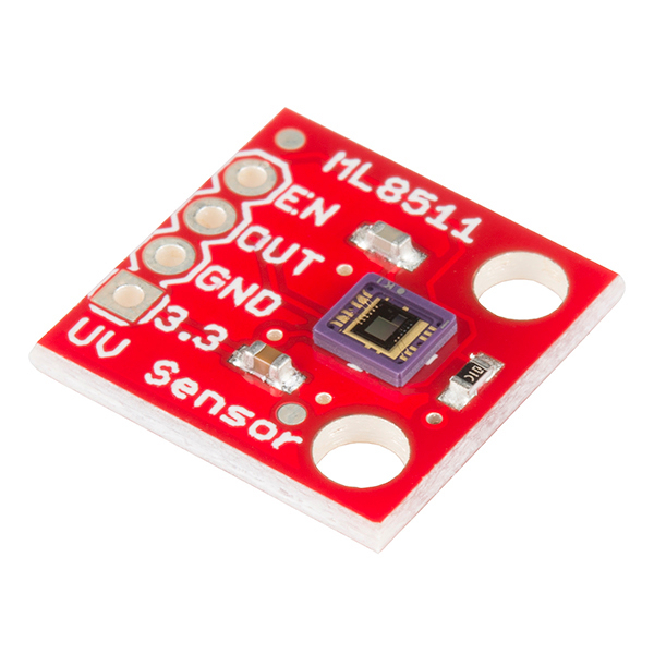
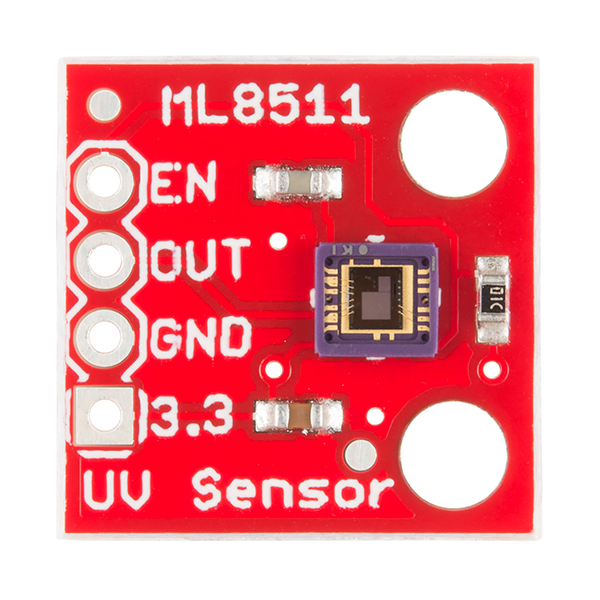
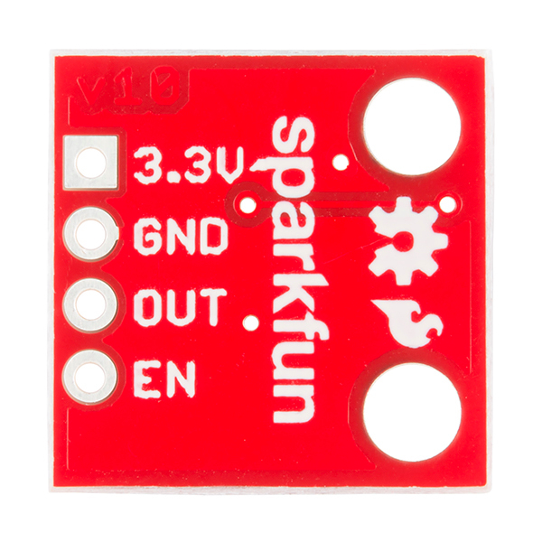
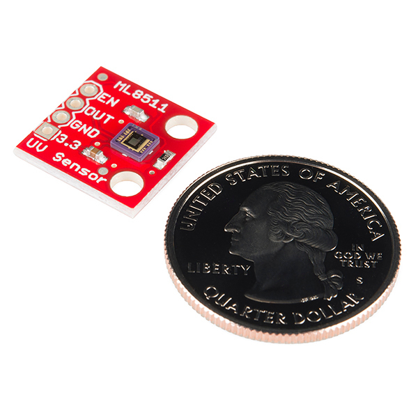
- SparkFun UV Sensor Breakout - ML8511

SparkFun UV Sensor Breakout - ML8511
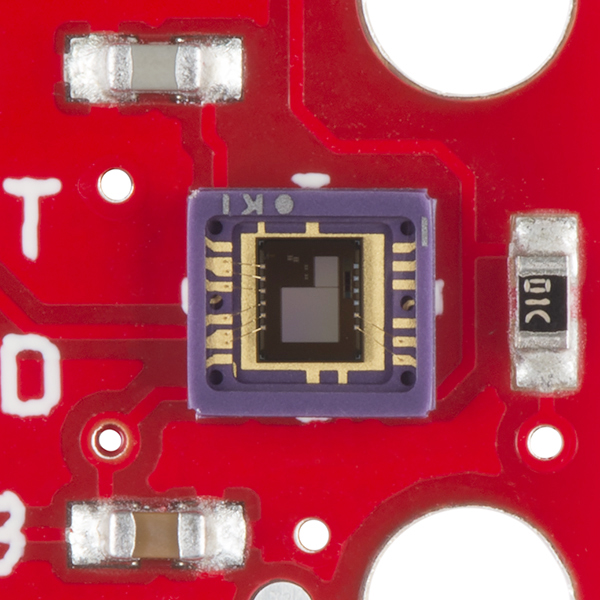
The ML8511 breakout is an easy to use ultraviolet light sensor. The MP8511 Sensor works by outputing an analog signal in relation to the amount of UV light that's detected. This breakout can be very handy in creating devices that warn the user of sunburn or detect the UV index as it relates to weather conditions.
This sensor detects 280-390nm light most effectively. This is categorized as part of the UVB (burning rays) spectrum and most of the UVA (tanning rays) spectrum. It outputs a analog voltage that is linearly related to the measured UV intensity (mW/cm2). If your microcontroller can do an analog to digital signal conversion then you can detect the level of UV!
- Schematic
- Eagle Files
- Datasheet
- Hookup Guide
- GitHub (Design Files & Example Code)
- Product Video
SparkFun UV Sensor Breakout - ML8511 Product Help and Resources
ML8511 UV Sensor Hookup Guide
March 13, 2014
Get up and running quickly with this simple to use UV sensor.
Core Skill: Soldering
This skill defines how difficult the soldering is on a particular product. It might be a couple simple solder joints, or require special reflow tools.
Skill Level: Noob - Some basic soldering is required, but it is limited to a just a few pins, basic through-hole soldering, and couple (if any) polarized components. A basic soldering iron is all you should need.
See all skill levels
Core Skill: Programming
If a board needs code or communicates somehow, you're going to need to know how to program or interface with it. The programming skill is all about communication and code.
Skill Level: Competent - The toolchain for programming is a bit more complex and will examples may not be explicitly provided for you. You will be required to have a fundamental knowledge of programming and be required to provide your own code. You may need to modify existing libraries or code to work with your specific hardware. Sensor and hardware interfaces will be SPI or I2C.
See all skill levels
Core Skill: Electrical Prototyping
If it requires power, you need to know how much, what all the pins do, and how to hook it up. You may need to reference datasheets, schematics, and know the ins and outs of electronics.
Skill Level: Rookie - You may be required to know a bit more about the component, such as orientation, or how to hook it up, in addition to power requirements. You will need to understand polarized components.
See all skill levels
Comments
Looking for answers to technical questions?
We welcome your comments and suggestions below. However, if you are looking for solutions to technical questions please see our Technical Assistance page.
Customer Reviews
5 out of 5
Based on 3 ratings:
3 of 3 found this helpful:
Science at 90000 feet!
The local high school is launching a high-altitude balloon as part of the senior physics class. We'll be using an ambient light sensor and this UV sensor with an Arduino to record conditions from the ground launch site until the balloon pops, around 80000 to 90000 feet. All the ground testing has been successful so we're ready to go!
Cool sensor!
I'm using this sensor in a sounding rocket. Since the rocket undergoes some roll, I am using three sensors 120 degrees apart along the main axis to get an accurate composite UV reading. These little sensors are ideal for my application, because they are analog and you can use as many as you have A/D pins on your microcontroller. I'm using the 3.3 pro-micro controller for its regulated voltage for accuracy and simplicity. Yet another cool breakout from SparkFun!
I’m looking for guidance in building an enclosure for this and the TSL2561 Luminosity sensor (https://www.sparkfun.com/products/12055) and the ISL29125 RGB sensor (https://www.sparkfun.com/products/12829) combined. My students are building a a light metering device for the school greenhouse and they are trying to determine what transparent material to use. They have decided to test glass, acrylic and polycarb and I am trying to get a sense of what they will find out before thaey test. (it allways pays to stay ahead of your students if you can!) Can anyone tell me how these materials might attenuate the incident light? Does anyone have any suggestions for other suitable “window” materials? Any help would be appreciated.
Please, declare the sensor accuracy?
A similar sensor that measures IR intensity in mW/cm2 would be pretty cool too!
The UV index is calculated by integrating along a weighting curve, meaning the intensity of some individual wavelengths will have a greater contribution to the overall index than others. A plot of this curve can be seen here. Unless this plot happens to exactly match the response curve of this particular sensor, then the UV index can not be precisely calculated.
Why not going the easy way? Get the UV measurements from the sensor (integrated through its specific spectrum with its own response curve), correlate them with "official" UVI records for yor location, and use the correlation to convert the readings into UVI estimates. My guess is that this approach, quite straightforward, wll render more than good enough results. (Reminder: it is of no use to calculate the UVI with three decimals).
This is what I had gathered from my research. I may see if I can use 3 or more of these with specific wavelength filters on them and then I may be able to use the weighted formula.
Hey Enigma - do you have a source for your formula? Would be good to have so we can learn more.
The sensor senses from 280-390nm so we won't be able to tell discrete wavelengths, just an intensity within this subset (280 to 390). That said, we should still be able to tell general exposure intensities and then integrate over time to put together a burn warning.
Theoretically, this sensor could be used with a diffraction grating to make a UV spectrometer. The diffraction grating should be capable of separating light in the 280-390nm range into fairly discrete wavelength bands. Slightly rotating the diffraction grating, say with a stepper motor, would align a specific band to shine on the sensor and the sensor would measure only that band's intensity. Of course, not being able to see UV light with our eyes does not help with a project like this.
It'd be neat if sparkfun sold tiny squares (suitable for capping these tiny IC sensors) of various wavelength pass filters all the way from UV to IR.
The datasheet has a responsivity curve on page 4, which doesn't appear to match the curve you posted.
The curve on the datasheet represents the measured intensity of the group of wavelengths (280-390nm). I believe Enigma is talking about about how 297nm photons contribute much greater to the 'UV index' calculation than 316nm photons. The ML8511 grabs them all and outputs a general intensity.
Nate - The source for my formula is a NOAA document regarding UV index calculation, available here. I believe the UV index calculation takes the relative damage that any one wavelength causes into account. After summing the contribution of each individual wavelength over the wide spectrum of UV light present in sunlight, you get a value that represents the total hazard for UV exposure on a linear scale (an index of 10 is twice as harmful as an index of 5). A higher UV intensity as read by this sensor would likely correlate with a higher index, but it might be difficult to directly correlate the two. As you indicated, you could integrate the value from this sensor over time to get a general measure of exposure, the trick would be finding out how much would pose a health or burn hazard. Any volunteers?? :)
Hello, would it be possible to obtain the schematics and code to connect the analog meter that is shown in the video? Thanks in advance.
how to measure the wavelengths using this sensor ?
Directly, you can't. The sensor is sensitive to a range of wavelengths. The sensitivity does change with wavelength, but you would need extremely careful calibration to correlate a measured value with a wavelength, and that is making the assumption that the intensity of all the to-be-measured wavelengths is equal.
See some of the other comments in this product page for some ways in which you may be able to measure wavelengths; they all depend on things like filters, diffraction gratings, and other external optics.
is it okay to use a PIC for this one? can someone help me how the conversion of analog to voltage will be made by using PIC microcontroller? we really need this for our project..
Thanks.
Will this be on Fritzing soon?
I just noticed this comment! There is a Fritzing part for this part.
Here's an Android App. for it. Uses BLE to connect to the android. I have the hardware using this breakout board working on a breadboard just need to makeout a board out of it.
and here's the hex file for it(uses Atmega328p 3.3v and nrf8001(use any breakout board available out there!)) >> Download it!
here are the connection's: a) nrf8001 breakout >> REQ 9 , RDYN 3 and RST 10 rest conventional SPI connections! b) sensor breakout >> output from the sensor A3 and the 3.3v reference A2
Request for IR intensity module ;)
enigma342, I think getting any 3 wavelengths and calculating their weighted mean can still be done as I think you answered your own question and as its also defined on this page >> http://en.wikipedia.org/wiki/Ultraviolet_index that mainly the wavelengths from 295nm to 325nm are to be valued because anyways the higher ones get absorbed anyway so one way is to presume that the sensor would anyways be receiving a major chunk of only the 295nm to 325nm spectrum and the rest is discarded! still we cant calculate the weighted mean because the respective values at each wavelength aren't available but we can assume and be like 70% correct.
I have 2 setups: a) 5v regular Arduino dev. board and, b) 3v3 ATmega328p with internal 8Mhz RC Osc. barebones on a breadboard .
I'm getting a MP8511 output of around 320 while I have the very same connections and code on the 3v3 and with everything all same on the setup a) I'm getting MP8511 output of around 200 , The reason for it being the AVCC difference. (I tested with the example code)
I found this document from the manufacturer on how to approximate UVI from this sensors output on digikey. http://media.digikey.com/pdf/Application%20Notes/Rohm%20Application%20Notes/ML8511_UV.pdf
From the photo, assuming larger square in the chip is the sensor, and the dimensions in the datasheet, it looks like the sensor size is 1 square millimetre. This makes it much larger than the units based on the GUVA-S12SD chip which has a sensor area of 0.076 square millimetre.
What would the advantage of a larger sensor be?
what enclosure do you recommend for outdor ?
A sensor that measures Solar Radiation in W/m2
"A similar sensor that measures IR intensity in mW/cm2 would be pretty cool too!"
A plain silicon solar cell + IR-pass filter would get you into the near IR.
The curve for the UV index measurement looks like it admits the wavelengths for UV-B and UV-C and does not provide for any measurement of UV-A. The response curve for this sensor looks like it will sense UV-A and UV-B but not UV-C. The UV-A sensitivity is probably a good thing because it could lead the user into being extra cautious about getting too much sun. The lack of UV-C would in theory cause a bias in the opposite (not careful enough) direction. But that depends on how much UV-C one actually has a chance of being exposed to (Wikipedia says: "completely absorbed by the ozone layer and atmosphere"). My gut feel is that this sensor will actually be pretty well suited for the job of helping us avoid UV exposure even if it won't support numerically accurate UV Index calculations.
How well would this sensor work as a flame/fire detector?
It would seem @heyjoe below is correct. I could not detect a flame with this chip. I would stick with IR (I am investigating the WiiMote sensor now)
I'm under the impression that fire does not emit much UV, but maybe in an otherwise closed environment? Try it! $13 to learn something new! EDIT: So apparently UV is used for flame detection, but this specific sensor may/may not work. See other comments.
Would be nice if you had LEDs with the proper wave lengths to go with this.. I need a bunch of them from 280-390nm..
Looks like the spectral response of this sensor may be too high for use as a flame detector. I understand that flame detectors in use now detect wavelengths lower than 300nm (http://en.wikipedia.org/wiki/Flame_detector). Don't know if this value is from precedence (what already being used) or from practical (what is best). Oh well, like the datasheet says, I could always use it for bicycle navigation (huh?)
Does anyone have an idea on the math to derive the UV index from the analog reading ? I have done some searching, and I am not sure it can even be done.
Found an article for calculating the UV Index, it takes into account elevation and cloud cover for the day which I think can be used to calculate back to the fluence rate (which from the short reading, is what this sensor is measuring [mW/cm^2] although the formal unit is [W/m^2]).
http://www.epa.gov/sunwise/uvicalc.html
http://www.google.com/url?sa=t&rct=j&q=&esrc=s&source=web&cd=2&cad=rja&uact=8&ved=0CDQQFjAB&url=http%3A%2F%2Fwww.researchgate.net%2Fpublication%2F230754106_Standardization_of_Methods_for_Fluence_UV_Dose_Determination_in_Bench-Scale_UV_Experiments%2Ffile%2F9fcfd503e8e2026e94.pdf&ei=qcVmU9v2NdGiyASusYGQCg&usg=AFQjCNGzhXJVF2JKwYFcaX_2IkCu7-z_vQ&sig2=WoZTzzL5dX41BKoNj5wKBw&bvm=bv.65788261,d.aWw
I am using the following sequence of conversions.
1) Get the voltage value: ((samples UV) / (samples @ 3.3V)) * 3.3
2) Get the current UV point based on mx + b. b is a positive offset of 1V (see page 3 of the data sheet "Output Voltage (Shading)") so we need to subtract it out and the slope I calculated around 8.33 (someone check my math), so:
((#1 above) - 1.0) * 8.33
This will give you a result in [mW/cm^2]. I'm not sure if this is a UV Index though, but judging that this sensor ranges between 0 and 15 [mW/cm^2] I'd say this very well could be the UV Index.
Again, someone double check my math....
The readings can provide "A" UV-index or a measurement of UV radiation (W/m2), not "THE" UV-index. The reason is that the UVI is calculated using weighed integration over a certain range of wavelengths (see f.eg. UV index in Wikipedia).