- Home
- Product Categories
- RF
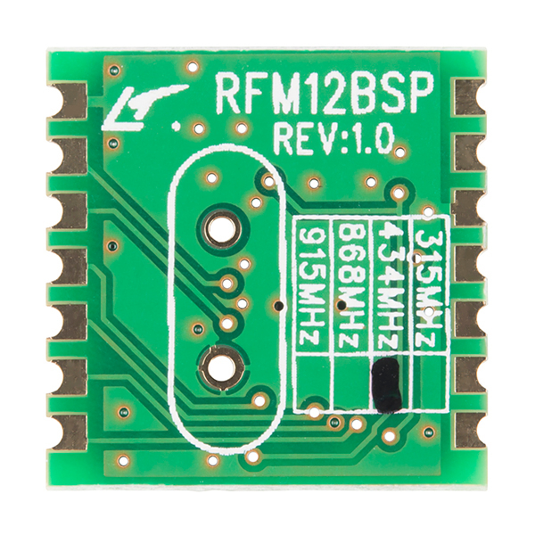
- RFM12BSP Wireless Transceiver - 434MHz

RFM12BSP Wireless Transceiver - 434MHz
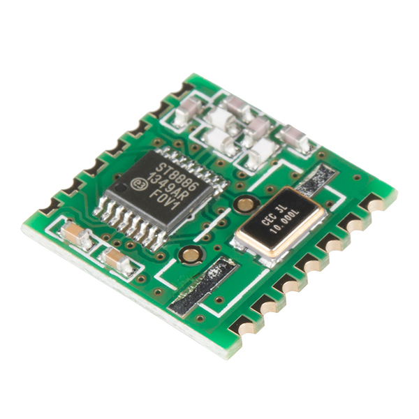
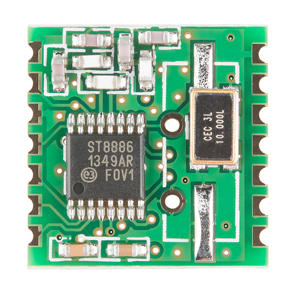
The RFM12BSP is a great inexpensive option for wireless communication; it's an ISM band FSK transceiver module implemented with a unique PLL. These modules operate in the 434MHZ band and fully comply with FCC and ETSI regulations.
This module has a wide voltage supply range of 2.2-3.8VDC. An SPI interface is used to send data and configure the RFM12 module. The configuration commands, described in the RF12 IC Datasheet linked below, can be used to set the data rate, frequency band, wake-up timer, transfer data, receive data from the 16-bit FIFO, and much more.
The module comes in a 14-pin SMD package, with pins spaced by 2mm. Check below for a breakout board.
- Low-cost, high-performance
- SPI compatible interface
- High data rate (up to 115.2 kbps in digital mode, 256 kbps in analog mode)
- Wakeup timer
- 2.2V-3.8V power supply
- Analog and digital RSSI outputs
- Differential antenna input/output
- Automatic antenna tuning
- 16-bit RX data FIFO
- PLL and zero IF technology
- Fast PLL lock time
- High resolution PLL with 2.5KHz step
- Programmable TX frequency deviation (from 15 to 240 kHz)
- Programmable receiver bandwidth (from 67 to 400 kHz)
- Analog and digital signal strength indicator
- Internal data filtering and clock recovery
- Clock and reset signal output for external MCU use
- 10MHz crystal for PLL timing
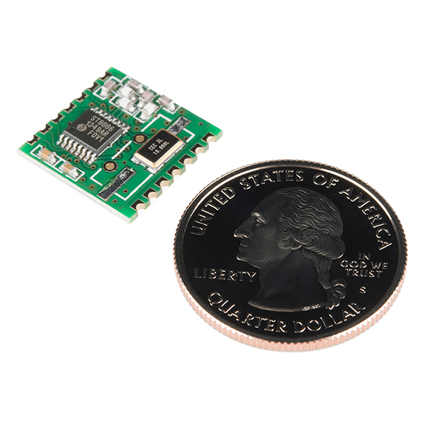
- 15.9 x 16.1 mm (0.626 x 0.634 in)
RFM12BSP Wireless Transceiver - 434MHz Product Help and Resources
Core Skill: Soldering
This skill defines how difficult the soldering is on a particular product. It might be a couple simple solder joints, or require special reflow tools.
Skill Level: Competent - You will encounter surface mount components and basic SMD soldering techniques are required.
See all skill levels
Core Skill: Programming
If a board needs code or communicates somehow, you're going to need to know how to program or interface with it. The programming skill is all about communication and code.
Skill Level: Competent - The toolchain for programming is a bit more complex and will examples may not be explicitly provided for you. You will be required to have a fundamental knowledge of programming and be required to provide your own code. You may need to modify existing libraries or code to work with your specific hardware. Sensor and hardware interfaces will be SPI or I2C.
See all skill levels
Core Skill: Electrical Prototyping
If it requires power, you need to know how much, what all the pins do, and how to hook it up. You may need to reference datasheets, schematics, and know the ins and outs of electronics.
Skill Level: Competent - You will be required to reference a datasheet or schematic to know how to use a component. Your knowledge of a datasheet will only require basic features like power requirements, pinouts, or communications type. Also, you may need a power supply that?s greater than 12V or more than 1A worth of current.
See all skill levels
Comments
Looking for answers to technical questions?
We welcome your comments and suggestions below. However, if you are looking for solutions to technical questions please see our Technical Assistance page.
Customer Reviews
No reviews yet.
This is a great tutorial with antenna references: http://blog.strobotics.com.au/2008/06/17/rfm12-tutorial-part2/
Great product and I have used both the 434mhz and 915mhz with no issues. One thing that I would like to point out is that you can get the exact same module in whatever quantity you want, directly from the manufacturer for about $4 with no manufacture lead time and 4 day shipping.
Do you mean rf-solutions or hoperf? I couldn't get a reply from hoperf for my e-mail.
Gaaah... it uses 2mm pin spacing! Why? For the love of God, why!!?? To use this, I'd need to buy a breakout board... which costs nearly as much as the module itself.
I made mine work in a breadboard by bending the tops of a breakout header to fit the spacing. Pins 1 and 14 (or was it 7 and 8...) aren't required for use with an ATMega - one is a 2nd GND that can be wired to the other ground without connecting the header, I don't remember what the other pin is... Anyway, that works somewhat. Agree about the breakout though - see my question below.
Just a heads up, but these models do not appear to be FCC, etc pre-certified. A statement within the product description ('fully comply with FCC and ETSI regulations") can be misinterpreted to mean a pre-certified... This means that although this module compiles with the FCC regulations using it within a commercial product will require formal FCC approvals which are quite costly.
If I am correct, and correct me if I'm wrong, I believe in the United States one must first acquire an amateur radio license of any class to transmit in the 70cm band (420-450MHz).
It's complicated but you are essentially correct that the 433MHz parts are intended for ISM region 1 (Europe, Africa, Mideast, Russia) while the 915MHz parts are intended for region 2 (Americas). There is considerable overlap and local differences that aren't covered in the above maps. These devices are designed to be low-power and noninterfering with other devices, so unless you're deploying a commercial product or a very large number of them this isn't likely to affect you directly.
While the statement is mostly true the FCC requires certification to Part 15 for just about anything you build - even if it is made up of compliant parts. Even if this radio bore a Part 15 certification you could not build a device using it and "inherit" an FCC certification.
Will there be a real breakout this time? The one 'below' is for the RFM22 which has more pins. Also, I assume the arduino thield for the 22 can't be used for the 12, or is the SPI and power pinout he same?
A couple of breakout board options were posted to the old product comments. Given this new product is just a mechnical change (or something) pressumably the old breakout boards should work just fine. The details were:
RFM12B Breakout Board PCB - solder yourself: http://modtronicsaustralia.com/shop/rfm12b-breakout-board-bare-pcb-rf-wireless-module/
RFM12B Breakout Board with soldered module: http://modtronicsaustralia.com/shop/rfm12b-breakout-board-wireless-module/
My wife purchased me a few of the older module RFM12B's SFE was selling and they are great! I'm going to need some more soon and was a bit worried they had gone EOL - I'm hoping with this new model it means that isn't a problem.
I'd googled breakout boards for these modules and had come up with one's listed above as well. I've got a couple and they seem to work really well for me.
They don't have plan to discontinue this module. Pls don't worry.
Wait a second... why does it say radio? i though it was supposed to be a food. Can anyone explain?
What's the operating range of these things?
It's all in the antenna. Google "DIY ground plane antenna". I've built a few of them and although they have no gain, the go miles farther than a whip.
Quite a bit actually. There are quite a few products using the Hope RF modules. Jeelabs, strobotics, openenergymonitor, lowpowerlab. etc.
Some details on range here: http://talk.jeelabs.net/topic/180
Google 'RFM12B range' (I think the unit above is similar, can't be sure as the datasheet links to the old module) for more info.
Don't expect much with a wire-whip antenna. The datasheet references application note "IA ISM-AN1" which seems to be relabeled by different manufacturers. There is comparison of different antenna types in table form for each of the bands. Google it. Unless someone else has already done some experimenting, there's no short answer, I'm afraid. (as far as I know)
Hi!, Anyone know what's the address of the control registers ?
Nevermind.
So this is the new version of the RFM12B, https://www.sparkfun.com/products/9582 ? It looks like the chip-on-board blob was changed to an SMD IC, but are there any other changes? Is it 100% compatible with the old RFM12B?
Yes, all the functions are the same as the old module. The only difference is IC package. The old one is with RF12B die and the new one is with packaged IC.