- Home
- Product Categories
- Beagle
- SparkFun BeagleBone Black Proto Cape


SparkFun BeagleBone Black Proto Cape
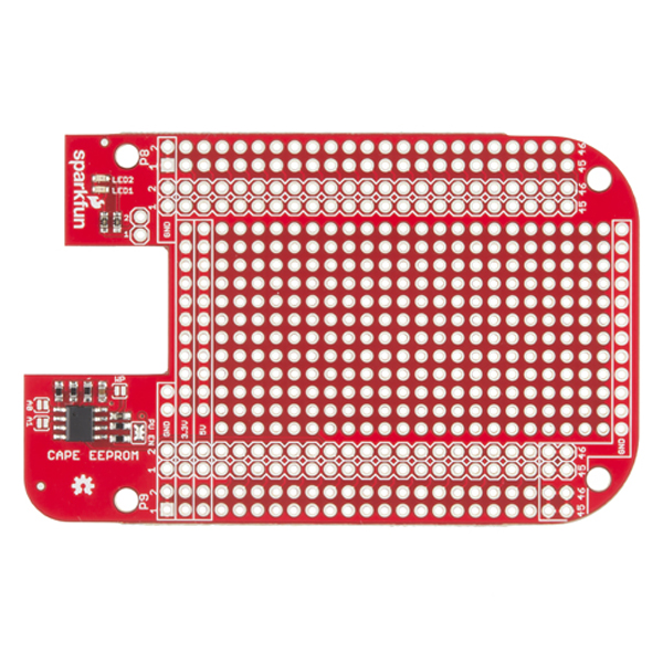
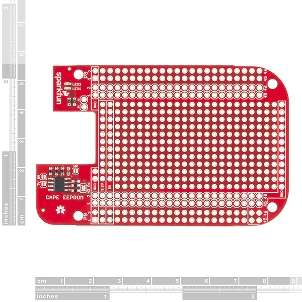
We all know the BeagleBone Black is pretty great, but wouldn't it be nice to create personal capes based on your needs? The SparkFun BeagleBone Black Proto Cape is a great way to prototype or design custom capes and provides you access to all gpio pins available on the BeagleBone Black. The Proto Cape easily mates with a BeagleBone Black and gives you a large prototyping area, two red LEDs for user applications or debugging, and access to a blank EEPROM that is great for storing pin configuration data.
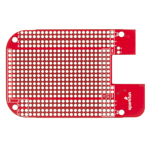
Each BeagleBone Black Proto Cape offers plenty of space to prototype with .1" spaced through-holes. There are two power buses provided along with ground connections on both sides of the board. With this cape you should have no trouble designing and creating whatever kind of add-on you would like to be attached to your BeagleBone Black.
Note: This cape does NOT include headers, we want to give you the option of choosing between which style fits your needs. 2x23 Pin Headers can be found in the Related Items section below.
- Large Prototyping Area
- 2 General Use LEDs
- 5V, 3.3V, & GND Pins Exposed on Both Sides of the Cape
- EEPROM Left Blank
- Schematic
- Eagle Files
- Datasheet (CAT24C256 EEPROM)
- Hookup Guide
- GitHub (Design Files)
- Product Video
SparkFun BeagleBone Black Proto Cape Product Help and Resources
BeagleBone Black Proto Cape Hookup Guide
May 22, 2014
Learn how to get started making your own capes for the BeaglBone Black using the BeagleBone Proto Cape.
Programming EEPROM
For an example of programming the Proto Cape's EEPROM check this link: https://github.com/jbdatko/eeprom_tutorial/blob/master/eeprom.md
Core Skill: Soldering
This skill defines how difficult the soldering is on a particular product. It might be a couple simple solder joints, or require special reflow tools.
Skill Level: Rookie - The number of pins increases, and you will have to determine polarity of components and some of the components might be a bit trickier or close together. You might need solder wick or flux.
See all skill levels
Core Skill: Electrical Prototyping
If it requires power, you need to know how much, what all the pins do, and how to hook it up. You may need to reference datasheets, schematics, and know the ins and outs of electronics.
Skill Level: Rookie - You may be required to know a bit more about the component, such as orientation, or how to hook it up, in addition to power requirements. You will need to understand polarized components.
See all skill levels
Comments
Looking for answers to technical questions?
We welcome your comments and suggestions below. However, if you are looking for solutions to technical questions please see our Technical Assistance page.
Customer Reviews
4.3 out of 5
Based on 4 ratings:
1 of 1 found this helpful:
Great, except for EEProm address conflicts, questionable documentation
I like the layout of the board, but something that isn't really clear is that the default EEPROM address could conflict with other capes. In particular, I'm referring to the 4.3" 4D systems LCD Cape. The documentation I found was that the addresses shouldn't conflict with each other (Proto Cape 0x57, LCD Cape 0x54). But, when these two capes are put together, the LCD Cape doesn't work. Suspecting a EEPROM address conflict, I shorted one of the address pins on the Proto Cape, and now it works. So, regarding the documentation, YMMV.
Aside from that, this cape works fine, and does what I want.
1 of 2 found this helpful:
Documentation Below Par
Mechanically and electrically good quality, but support somewhat lacking.
This product will serve well as a primer for the buyer to learn about developing BBB Capes from the ground up.
But if the intention of the purchase was to use this product as a tool to clean up BBB wiring and move rapidly toward a specific goal, the documentation is inadequate for this purpose.
An email to SFE Support resulted in a rapid response with a redundant suggestion to read the Hookup Guide.
So, "Okay", but no better.
Sure, we can Google all day long and eventually find some cogent and complete information, but that means many customers are forced to repeat the work SFE could have done ONCE to find and provide pertinent URLs.
Hi, Proto boards can be used to build up any circuit or design that you can think of. Our docs go over setting up the board to plug into the BBB, but for details on a specific use, you will need to do some research on that subject or project goal. Happy hacking
Perfect for my needs
My team has a few boards of a first-iteration custom-designed cape, on which we did not include the EEPROM (an oversight on our part!). We used this cape as a retrofit add-on to this custom board to give it self-ID capability, as well as to store calibration data. Slick!
Solves important problem
I appreciate this cape for solving the problem of how to make robust attachments to the BeagleBone Black pins. Instead of relying on wires pressed into the BeagleBone pins, you can solder them to this board, and by using the associated 46-pin headers, have a much more robust connection to the BeagleBone.
The central prototyping area (rectangular grid of holes) - are those holes all isolated from each other, or are any connected together? For example, the Schmartboard cape has a diagram showing the holes are connected together in groups of five
Unfortunately, I can't post a screenshot of board layout from the Eagle file. However, if you want, the file is available under the Documents tab and Eagle does have a free maker license that you can use. Just open the
.brdfile.Otherwise, the two double-stacks of outlined pins mirror the connections to the Beaglebone. Additionally, the pins outlined by boxes also share a connection (they should be labeled). I hope this information helps. If you have any more technical questions, please use the link in the banner above, to get started with posting a topic in our forums. Our technical support team will do their best to assist you.
I believe there are a few small typos on the P9/P8 headers as they relate to the GPIOs.
*P9
PIN 14 -- GPIO_50 (currently marked as GPIO_40. It is port gpio1[18] => 1*32+18 = 50)
PIN 17 -- GPIO_5 (currently marked as GPIO_4)
PIN 18 -- GPIO_4 (currently marked as GPIO_5)
PIN 27-31 -- GPIO all marked in the 12x's, should be 11x's
These have been verified on the table/datasheet provided by BBB. Although, I have yet to check the software files relate as mentioned above.
If the schematics are ever revised, or future capes designed it would be great to see this rev'ed! Cheers.
I don't think the 4k7 sda, scl pull-up resistors meet the bbb system reference manual requirement for 5k6 parts.
I just picked up a few of these to start doing some prototyping with. The power connector on the BBB seems to be in the way keeping it from seating all the way. It stops about 1/8" short. Is this an intended "feature" or am I missing something?
Interesting, I have one on my desk and it looks just fine. Can you give me more info on the headers and the version of BeagleBone you are using? It's possible that BeagleBone changed connectors on us. I'll see what I can find out. Thanks for bringing this up.
I have a Beaglebone Black RevC from Element14. The headers I'm using are in the stackable 2x23 header found in the "Also Purchased" column to the right. The headers on the board have the same height as the stackable headers. I also tried it on a Rev A and it seems to have the same issue. Should the proto cape be able to sit flat against the header on the Beaglebone without a header soldiered to it? Thanks for looking into this.
Ah, I think I understand your question better, you will have a small gap between the board and the BBB connector using the stackable headers. With non stacking headers PRT-12791, the plastic holder takes up the space between the BBB and the bottom of the PCB. I hope this helps!
I just got a proto cape and have added stackable headers. I plug it into my BeagleBone Black, running the 2014-11-11 image of Debian and run i2cdetect I get:
UU's are showing up where I expect the cape EEPROM to be. But the UU's show up even if the cape isn't attached.
What should I do?
--Mark
Hey Mark,
Casey is spot-on, the BeagleBone reserves those four i2c addresses for cape EEPROMs and it prevents any other kernel module from instantiating at that location. I would always expect to see that result from i2c-detect with or without that proto-cape.
BTW, there is a very good tutorial on BBB capes here and I wrote a tutorial on some BBB i2c specific issues.
I believe all the address blocks are blocked out so you don't try to use a device on those. I'll see if Josh will chime in with more info.
If anyone has trouble with the address bits, note that the unsoldered pads represent a 1 in the address table. Soldering them changes them to 0. It makes sense if you look at the default address of 0x57 with no pads jumpered. Normally the eeprom keeps these low, but the proto cape has pullups so they are high by default.
One note is that the board is about 1mm too long to fit neatly into the Adafruit BoneBox. Just in the bit with the EEPROM on it.
Else excellent product and easy to use.
I purchased this cape. Apparently I can write a dts file and compile it so that I have better control of the headers at boot time. I'm trying to control some dc motors and was only able to find 4 gpios and 4 more pwms that are low and stay low when the beaglebone boots. I can use those for now, but I imagine that in the future this will probably change and I'd like to know how to deal with it. I'd also like to be able to choose my pin layout so that it's a little more intuitive for my students.
So my questions are:
Can I access and program the eeprom on the proto cape from the beaglebone black? If so, how?
How do I make the dts file?
How do I compile it?
Where do I put it?
How do I make debian use it when it boots?
I started making a tutorial for BBB Cape EEPROMs here. If you can get the May 2014 Issue of Linux Journal, I wrote about the device tree in some more depth. I don't think I can release the text to you myself, sorry.
Also, the Beagle device tree system has changed a bit. They used to keep stuff in
/lib/firmware, which is where I think you can still drop your compiled DTB. The majority of the AM335x device tree, included capes, appears to be folded into a master file, the location of which I am not sure.As recommended below, [Derek Molloy](here: http://derekmolloy.ie/gpios-on-the-beaglebone-black-using-device-tree-overlays/ ) has some excellent tutorials.
You approach is sound though. Once you have the EEPROM matching with your DTBO, the BBB will boot and automatically pin mux your cape.
I was frustated with this product with BBB Debian image..... but with BBB Angstrom was a breeze to make the BBB recognize the cap and use the device tree mecanism. What is wrong with BBB Debian image not working with this product?
See "Loading custom capes" here for information on a bug when loading custom capes.
Loading custom capes
Found many infos here: http://derekmolloy.ie/gpios-on-the-beaglebone-black-using-device-tree-overlays/ http://papermint-designs.com/community/node/338
What size breadboard would fit with stackable female headers populated?
The description states that the EEPROM is blank, however, at least one of these that I purchased came programmed as a "SparkFunBB-BONE-CRYPTO2014", presumably intended for SF's new CryptoCape DEV-12773.
Update: Some boards went out with CryptoCape data on the EEPROM. It won't harm anything but I am working on a quick script to erase it.
Thanks for the heads up! I will double check our production files.
I'm sure someone will ask, since SFE weren't particularly explicit in the description; it's a 256kb I²C EEPROM (according to the part number/datasheet).
Correct. It's a run of the mill EEPROM for board identification.