- Home
- Product Categories
- Distance
- SparkFun ToF Range Finder Sensor - VL6180

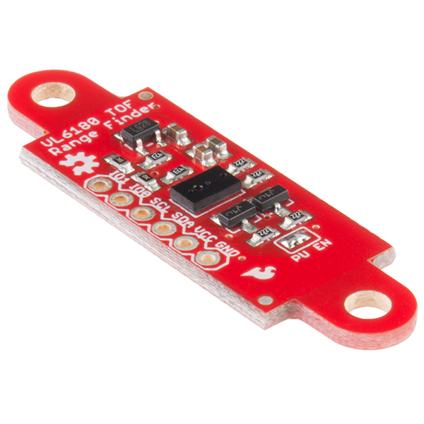
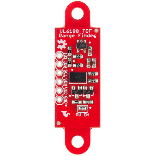
SparkFun ToF Range Finder Sensor - VL6180
This is the SparkFun "Time-of-Flight" Range Finder, a sensor board for the VL6180 distance sensor. Unlike most distance sensors that rely on reflected light intensity or reflected angles to determine range, the VL6180 uses a precise clock to measure the time it takes light to bounce back from a surface. This affords the ToF Range Finder and VL6180 a great benefit over other methods because it can be much more accurate and more immune to noise. Does this technology sound familiar? Well it should, it's the same means cellphones use to detect when the caller is holding their phone to their ear.
The VL6180 from STMicroelectronics is actually a 3-in-1 package that combines an IR emitter, a range sensor, and an ambient light sensor together for you to easily use and communicate with via an I2C interface. The ToF Range Finder is very similar to its breakout cousin with a few important differences. What sets this board apart is this sensor is equipped with an on-board 2.8V regulator, which means if you were to plug in a voltage higher than 2.8V it will be shifted down without worry of damaging your board! Another thing to note is the form factor of the sensor itself. Many small robotics platforms have integrated hole patterns for the long time favorite Sharp IR sensor line. This allows the VL6180 Sensor to be a near drop-in replacement for most Sharp sensors.
Note: Though the datasheet states the VL6180 measures an absolute range of up to 10cm, we have successfully tested it up to 25cm. The more you know.
- 2.8V Regulator - Provides the required 2.8V for the sensor
- I2C Level Shifter - Provides logic level conversion from 2.8V to VCC
- 3-in-1 Module
- IR Emitter
- Range Sensor
- Ambient Light Sensor
- Measures absolute range up to 10cm
- Gesture Recognition
- I2C Interface
- Two Programmable GPIO
- Sharp Sensor Board Layout
- Schematic
- Eagle Files
- Hookup Guide
- Datasheet (VL6180)
- Application Note (VL6180)
- GitHub (Design Files & Example Code)
- GitHub (Library)
SparkFun ToF Range Finder Sensor - VL6180 Product Help and Resources
VL6180 Hookup Guide
February 12, 2015
Get started with your VL6180 based sensor or the VL6180 breakout board.
Core Skill: Soldering
This skill defines how difficult the soldering is on a particular product. It might be a couple simple solder joints, or require special reflow tools.
Skill Level: Noob - Some basic soldering is required, but it is limited to a just a few pins, basic through-hole soldering, and couple (if any) polarized components. A basic soldering iron is all you should need.
See all skill levels
Core Skill: Programming
If a board needs code or communicates somehow, you're going to need to know how to program or interface with it. The programming skill is all about communication and code.
Skill Level: Competent - The toolchain for programming is a bit more complex and will examples may not be explicitly provided for you. You will be required to have a fundamental knowledge of programming and be required to provide your own code. You may need to modify existing libraries or code to work with your specific hardware. Sensor and hardware interfaces will be SPI or I2C.
See all skill levels
Core Skill: Electrical Prototyping
If it requires power, you need to know how much, what all the pins do, and how to hook it up. You may need to reference datasheets, schematics, and know the ins and outs of electronics.
Skill Level: Rookie - You may be required to know a bit more about the component, such as orientation, or how to hook it up, in addition to power requirements. You will need to understand polarized components.
See all skill levels
Comments
Looking for answers to technical questions?
We welcome your comments and suggestions below. However, if you are looking for solutions to technical questions please see our Technical Assistance page.
Customer Reviews
4.3 out of 5
Based on 10 ratings:
1 of 1 found this helpful:
I love this sensor
Previously I was using HC-SR04 sensors and getting really frustrated with the lousy quality I was seeing with those. I decided to spend a little more money and try this one out. I have not been disappointed with the quality. I wish it had a slightly longer range, but for my purposes (robot that doesn't want to bump into things), it has been fine. It has a very narrow sensing band, so be aware of that.
Of course, after trying one out, I decided to use more on my robot, but was very surprised that I could not set the I2C address on the device to allow multiple instances. I think this is a failing of the actual VL6180 chip, not the Sparkfun design.
I took the advice from review of Member #689272 and designed a circuit using the multiplexer breakout board to select from multiple sensors on the I2C bus. You can find the details here:
https://plus.google.com/+MarkWomack0/posts/XxheCZJMx8S
Hope you find it useful. I am going to integrate this into my robot.
1 of 1 found this helpful:
Very useful, not too hard to figure out how to make it work.
I connected this to the i2c-1 buss on a Raspberry Pi, and it showed up right away in i2cdetect -y 1 at 0x29, so that was really easy. The 3.3V spec fits very well with the Raspberry Pi, not much risk of any damage.
Next was to program the device. Using I2C_RDWR ioctl(2) calls, I made it work with the 16-bit register addressing. I was able to write and read the registers correctly, and set-up with the long sequence of magic values listed in the appnote chapter 9. Once that was done, it was ready to measure distances, using the programming logic shown in the app-note. Just from some quick checks on the desktop, it looked like it was most accurate up to about 200 mm, but it did return reasonable values beyond that. Once past 255 mm there would be various bits shown in the status register, that showed that its range was exceeded.
For the ambient light, the similar 1-shot algorithm was used, just referring to the ambient light registers instead. I am getting some numbers (counts from register 0x050-0x051) which depend on the ambient light level, but so far no conversion from these to lux or intensity numbers.
4 of 4 found this helpful:
great sensor but no I2C address change
This sensor works well and is more precise than your typical Sharp IR sensors. The only downside (Apart from price) is that allthough you can change the I2C address, the new address is stored in volatile memory so it's gone after a restart. (-1 star)
For everybody who is wondering how to use multiple sensors, I made this work with the MUX breakout (https://www.sparkfun.com/products/9056): Just tie the SCL lines together and route the SDA through the multiplexer. For many sensors, you will want to remove the pull up bridge (PU EN) and use your own 10kOhm for SCL and SDA (input side of multiplexer) Don't forget to init each sensor before starting to read them or you will get too low readings!
Pretty darned handy...
I was looking for a position sensor that I could use in a variety of vehicles to measure throttle position for stationary simulation tasks. After wiring it up and realizing that I had to use an UNO rather than a MEGA ADK board, it works like a champ. Small, non-contact, inexpensive, and flexible. Good alternative to linear actuators for this application. Compatibility with the other boards would make it more useful for me and warrant an Excellent rating. Still, I can't complain. Great product. Thanks, SparkFun!
In the right place this is a giant step up
Its fanastic to have to board, didn't need to think about voltage regulation or logic shifting. And loved that it gave me distance in mm, it was a giant stepup from using an IR device and wanting to know where objects where. Main thing here is that I didn't need to calibrate. One place that I don't think this is as useful as a standard IR device, that just gives reflectance, is when you have other objects that are partially blocking the view of the beam here is seems that the objects that are partially blocking give the distance measurement even though they are static. IR reflectance on the other hand can be tuned to the background reflectance and then if another object comes along you can see the increase in reflectance. Maybe there is a way to get around this but I need more investigation. Still its great to have distance and the library and instruction where very clear, had it up and running and in the sculpture in no time at all :)
one other note - is that I too would like to have several I2C addresses possible.
Seems to work well
I got it tested in 10min. Using this for a auto faucet so I still need to see how it handles with some nearby physical interference. Provided Arduino library helped make this easy to run.
VL6180 Review
I was able to write Spin code for the Parallax Propeller to read distance and ambient light with a few problems. I stole liberally from the SparkFun Arduino code. I was not able to change the I2C address. If it is changeable but resets to default on power cycle, that is a nonstarter.
Hi, Looking over the datasheet, I found a note about this. Take a look - "super_i2c_slave__device_address: User programmable I2C address (7-bit). Device address can be re-designated after power-up". More information can be found in the datasheet
I like it
The VL6180 sensor provides a more stable measurement than similar devices. I compared the VL6180 with Parallax PING, Sparkfun HC-SR04 and Sharp GP2Y0A21YK0F using a Pololu AStar 32U4 Prime LV microcontroller. The result was free of noise and jitter. I would recommend this product to folks considering obstacle avoiding and/or wall maze robotics. I found it works great replacing the PING on a servomotor without reducing battery lifespan.
pretty nice
Not something SparkFun can do anything about but I'd love it if the thing worked for greater distances.
I'm having a bit of trouble with the crosstalk calibration going through IR Lexan 121 but otherwise it works well.
I'd not be interested in this but one thing I might suggest is a version with an m0 or some other cheap microcontroller that handles the i2c and exposes an analog voltage to users instead so it really can be a drop-in replacement for the Sharp sensors.
To the same end, it might be nice to have a version with the sensor off-center so it's exactly where the IR sensor would be in the Sharp sensors.
Generally cool, though.
Time of Flight Sensor
Configured it to work with an FPGA with IIC interface driven from PC to USB to UART interface. Setup worked and allowed simple reads and writes to the sensor, Had to run the app note register initialization sequence, then conversions worked. Was intermittent until I fully followed the recommended polling, read and clear sequence. Range I got with the recommended settings was 0" to ~8". Gives an 8 bit value from near 0 to around C4 hex, any farther than 8 inches gives FF hex code. Haven't played with other than recommended initialization reg settings yet.
Hello, is there anybody who uses this sensor in Simulink? I cannot figure out how to make it work. Could anyone help me out or is there a Link to a side which could help me?
I designed a 3D printable side strut for the Shadow Chassis that mounts this VL6180 and replaces the existing side struts. This allows you to mount the VL6180 sensor on the front or rear of any robot you are designing. You can find the part here: http://www.thingiverse.com/thing:1196071
I have bought a Sparkfun VL6180 Sensor Board and connected it to a STM32F415 MikroE Mini M4 MCU. I can correctly talk to it by asking the Model ID, (which returns 0xB4 correctly), but the RESULT_RANGE_STATUS register (0x4D) always returns 0x19 (0b00011001) which according to the VL6180 datasheet means that it has a VCSEL continuity error (bits 7:4 or 0b0001). I have gotten this with both a VL6180 sensor (which has the 2.8V DC regulator) and with another VL6180 breakout (without the regulator). Is anyone else experiencing this problem?
Anyone have success modifying the library to read the full 60 cm?
It's not documented in the datasheet but implies that you can achieve that level of range at lower resolution and high noise.
The "datasheet" link links to the product brief, which is only 4 pages long. The full datasheet is 79 pages.
I see it can measure to 50cm accurately, but what does that mean? What resolution does it have? Can I detect within 1/50 of a centimeter or so? Thank you.
"Ranging beyond 100mm is possible with certain target reflectances and ambient conditions but not guaranteed" (sic datasheet)
During my testing, it was accurate within 5 mm if you stayed withing the 100 mm range that it says is the most optimal.
The "Typical ranging performance" graph in the datasheet only goes to 150mm. Don't expect accuracy higher than 1cm (which is quite good!).
I'm running into frustration trying to get this board working. I'm not using an Arduino -- just programming a TI CC2530 using C to work with this board. The easy part was hookup and getting I2C working: it's straightforward writing and reading registers, even R/W with multiple registers works fine (able to confirm writes to config parameters reading them back). However, the program gets stuck trying to start ranging -- the board doesn't respond by actually doing the ranging. That is, after writing 0x01 to SYSRANGE_START, repeated reading of RESULT__INTERRUPT_STATUS_GPIO doesn't post the sample ready bit. Naturally, I suspected that something I failed to set up properly was the cause. I tried for some hours variations of adding some busy-waits for microseconds here and there, repeating the writes, and so on, hoping to luck in to a resolution. Here's the fun part: sometimes (nondetermistically, I haven't found a pattern yet) the device does actually complete the range, and it looks like a reasonable number of millimeters. Invariably the single range is stuck at its one-time range thereafter (until poweroff and restart). Had it not been for these rare cases where ranging works, I would suspect some parameter error. As it is, either there is a timing problem, a power problem, or the unit is flaky. Is there some way to make progress on this? Is the only answer that one simply has to use a duino?
For those who've used this, exactly how precise are the measurements? Are we talking fractions of a millimeter? I see a lot of talk about accuracy in the comments, and I'm not sure if people are referring to accuracy or precision. Accuracy isn't so important for me, as my needs are specifically measuring relative distance changes. So is there an actual spec for the precision/resolution, or can someone definitively post just how precise they're able to get with their own tests?
what is the measurement frequency of this?
These are great little sensors that have been using for about a year now. They can be mounted on a super small board which can be soldered directly to a Teensy or Pro Mini and digitalWrite(HIGH) is sufficient to provide power to the board. This means that touchless gesture control can replace switches and buttons for a variety of applications. Working, well-commented sketch that outputs distance and lux is here: https://github.com/kriswiner/VL6180X. Appallingly small boards can be found here: https://www.tindie.com/products/onehorse/vl6180x-proximity-sensor-via-ir-laser-range-finding/.
Any idea how I could hook this up to a Raspberry Pi, using a Python script?
Can this be used to detect eye blinks if i try to just measure disturbance in the signal when the eyelid closes and opens? Would shining this on the cornea be problematic?
I love the "Sharp Sensor Board Layout".
Will this be able to measure water levels? Does water reflect enough IR for it to work in this application? Also, is this safe to use in humid environments?
I think water is a pretty difficult target. It has lower index-of-refraction than most other things, so it reflects less than half of what a window reflects. The new datasheet says 'no washing, it's not sealed' for the soldering process , so I think living full-time inside a fluid tank is highly unguaranteed. Spending power to keep it always 5-10c warmer than the environment might help.
It's not clear to me how you can use more than one of these on an I2C bus since they would all use the same address. Many I2C devices have address bits which can be used to give a range of 4 or 8 addresses. Is there some other way to use 4 or more of these on the same I2C bus?
I've used this switch in the past to address multiple devices on the same I2C bus- http://www.maximintegrated.com/en/app-notes/index.mvp/id/1073
From the application note: Communication with the VL6180X is via the I²C bus. The default 7-bit address of the VL6180X is 0x29. It can be changed by the user to any 7-bit addresses by writing to the I2C_SLAVE__DEVICE_ADDRESS {0x212} register.
There is a way to use multiple sensors but it relies on the bring-up of the device. You can change the address of the device after boot, but this is not stored in non-volatile memory. When you power cycle the device the address you select will be reverted back to the default address. You will need to power each device up individually and change the address. There is a way to do this with the GPIO pins to enable/disable devices. I am currently working on a section to add to the hookup guide that will address this better.
I2C multiplexer is the answer here:
https://www.tindie.com/products/onehorse/tca9548a-i2c-multiplexer/
Will this give out a number or will it give me multiple pulses if it passes through a translucent material? I would like to get 2 to 3 reflections as it passes through a clear plastic. That would be the front surface, the back surface, and the surface behind that.
I suspect this unit scans from short delay/distance to longer, looking for correlations. It looks like it stops and reports the distance as soon as it decides it had found a correlation, but it won't keep scanning after that. Maybe it could scan for multiples if reprogrammed internally; maybe with the mfr eval board? Then there would be fuzzy limits between smeared and distinct responses...
Please update the datasheet or link thereto. The current link points to a preliminary data brief. Mouser links to a datasheet at http://www.mouser.com/ds/2/389/DM00112632-490369.pdf .
In the application note, it talks about three different timing quantities: signal rate, convergence and sample rate. What I'm interested in is how many measurements can you take per second? I realize that it will vary with the distance being measured, but is there a worst case? Is there a formula for a given distance? Would this sensor work on a target that is constantly moving, but always within the measurement range?
The library I wrote takes a sample about every 100ms, with some tweaking you can get it down to about 10ms.
Sparkfun, it is actually cheaper and way more flexible to go with STM's own dev kit!
http://ca.mouser.com/ProductDetail/STMicroelectronics/EVALKIT-VL6180X/?qs=sGAEpiMZZMvfpQN6QVmrfGjb%252b49cDybCa83Lgq8kEXU%3d
Different applications. The evaluation board is much bigger than this board and is meant to help you learn how to use the chip. This board is meant for use in actually installing the chip into something useful.
I think the point was that the eval kit has more to it, yet is cheaper. Sure this is smaller, has less components overall, and is intended for use in a prototype, but why does it need to be more expensive with fewer things going into it? (Before you even think it, yes, design time, making the boards, etc does cost, but the dev kit has more of all that too due to its complexity.)
The advert in my email said "allows absolute distance to be measured independent of target reflectance. It can measure off just about any material". Here, it says it bounces IR light off the target and measures time of flight. OK, but how is that independent of target reflectance? If the target reflects too little light, then you have too little signal, it is dependent on materials with enough reflectance to measure.
There is an ALS sensor that compensates for low light levels. The laser inside the module is quite powerful and the detector is tuned to see it. Indoors, it should work great. It is supposed to work outside but we have not done extensive testing. This sensor is typically found in cellphones to detect when you are holding it to your ear.
According to the description it measures the "Time-of-Flight", so only the time the light travels matters not the amount of light reflected.
The schematic incorrectly shows 3.3V for the voltage regulator. Should be 2.8V, which agrees with the marking in the pictures.
There's an Appnote on performance/tracking with graphs that answer some of these questions.
How wide is the beam spread (for lack of a better word)? How small of an object can this thing detect?
I hope those two questions are actually asking the same thing. I'm wondering: if I put this on a rotating platform, how accurately can I resolve an environment around the sensor, and at what sample rate.
Two different questions. If you look at the actual data sheet, it appears to have what they call a "view cone" of 25 degrees. As to how small of a thing it will respond to inside that cone, I haven't found anything.
Sounds like what you want to do is go to Target and buy a Neato vacuum cleaner and give it a LiDAR-ectomy.
It seems to use a laser for the IR emitter, so I guess the half angle would be a couple of milliradians. However this is in contradiction with a drawing in the datasheet indicating an opening cone of 25°. IMO it's next to impossible to open a milliradian laser beam that wide with lenses.
For measuring short distances, what is the minimum distance and resolution it can detect?
From the app note, it looks like < 10 mm is not so good, and with a lot of averaging you could get to around 1mm, but looking at the apparent noise in the graph, I'd bet on more like 2-3mm.
dont you have a video of using this one?
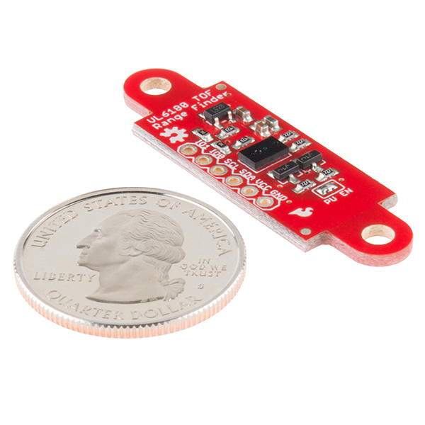
It would have been nice if the eyelets were V-cut, so that they could easily be broken off, if you only need the rectangular board.
There is a version only with the sensor on https://www.sparkfun.com/products/12784
But that doesn't have the voltage regulator and level shifters
In the hookup guide we show how to use a simple lm317 and a 3.3v pro-mini to make connections. It's a hack at best but does alright.
There's also some technical differences. I think voltage regulators. They are not a complete 1:1.