- Home
- Product Categories
- Imaging
- SparkFun RGB Light Sensor - ISL29125

SparkFun RGB Light Sensor - ISL29125
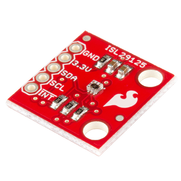
If you’ve had ideas for a project that depends on the ability to sense different spectrums of visible light and react based on those measurements, the ISL29125 breakout board may be just what you need. The ISL29125 breakout board makes it very easy to sense and record the light intensity of the general red, green, and blue spectrums of visible light while rejecting IR from light sources. You can then use these color sensor readings for the purposes of logging and finding patterns, or creatively calculate and make control decisions in your electronic projects.
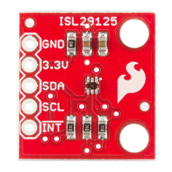
Each pin from the ISL29125 has been broken out to allow you to interface with it, SDA, SCL, 3.3V, GND, and even an optional INT pin is available for use. The ISL29125 Light Sensor operates at 3.3V but if you plan on using this chip with a 5V microcontroller make sure to use a logic level converter.
- Operating Voltage: 3.3V
- Operating Current: 56µA
- Selectable Range
- I2C (SMBus compatible) Output
- ADC Resolution 16 bits
- SCL, SDA, INT, 3.3V, & GND Pins Broken Out
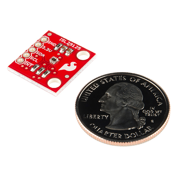
- 18.4mm x 17.2mm x 2.4mm (0.7" x 0.6" x 0.09")
- Schematic
- Eagle Files
- Hookup Guide
- Datasheet (ISL29125)
- GitHub (Design Files & Example Code)
- GitHub (Library)
SparkFun RGB Light Sensor - ISL29125 Product Help and Resources
ISL29125 RGB Light Sensor Hookup Guide
June 12, 2014
A guide to help you integrate the ISL29125 RGB light sensor breakout board into your electronic projects.
Core Skill: Soldering
This skill defines how difficult the soldering is on a particular product. It might be a couple simple solder joints, or require special reflow tools.
Skill Level: Noob - Some basic soldering is required, but it is limited to a just a few pins, basic through-hole soldering, and couple (if any) polarized components. A basic soldering iron is all you should need.
See all skill levels
Core Skill: Programming
If a board needs code or communicates somehow, you're going to need to know how to program or interface with it. The programming skill is all about communication and code.
Skill Level: Competent - The toolchain for programming is a bit more complex and will examples may not be explicitly provided for you. You will be required to have a fundamental knowledge of programming and be required to provide your own code. You may need to modify existing libraries or code to work with your specific hardware. Sensor and hardware interfaces will be SPI or I2C.
See all skill levels
Core Skill: Electrical Prototyping
If it requires power, you need to know how much, what all the pins do, and how to hook it up. You may need to reference datasheets, schematics, and know the ins and outs of electronics.
Skill Level: Rookie - You may be required to know a bit more about the component, such as orientation, or how to hook it up, in addition to power requirements. You will need to understand polarized components.
See all skill levels
Comments
Looking for answers to technical questions?
We welcome your comments and suggestions below. However, if you are looking for solutions to technical questions please see our Technical Assistance page.
Customer Reviews
4.5 out of 5
Based on 2 ratings:
Great product
I was needed a sensor which reads color and return the color from my Arduino board. It easy to setup and use.
It works
good sensor, works as advertised, Limited documentation on applications and how to interpret the data that it reads.
I've managed to get the Arduino to read values from the sensor, but it only returns FFFF. Is it possible I've damaged something on the board, or do I just not have the libraries installed properly?
did you figure out the issue.
I'm having the same issue. did you ever figure it out?
Did you figure out the issue?
If you are using a 5v arduino board, make sure you have its 3.3v out running to the LV side of the logic converter
the sensor is returning FFFF . why am i getting this error
*spectra
Hi! Is there a way to change the I2C address? I'd like to use 6+ color sensors in my project.
You could always add a I2C multiplexer: https://www.sparkfun.com/products/14257
Hi I cannot read any RGB vals even though i connected everything as in the Hookup guide. I think the problem is in the “.init()” function because it never prints : "Sensor Initialization Successful\n\r" What can I do?
First off make sure you have installed the libraries for Arduino correctly. If you have you should start by taking a scope and looking at the SDA and SCL lines. SCL should just be a clock, but by looking at the SDA line you can see the starts, bytes, ACKs and stops. That can at least give you an idea if the sensor is responding to the master. If you aren't getting any response, make sure you have SDA and SCL correct. If you never see the SDA line get a response, it could be the sensor.
I am struggling to use this device to read blocks(red, blue, green, and yellow).
I have tried various combinations of settings with little success. When reading any color I get semi-unique readings(but not unique enough to differentiate from some of the other colors). The thing is even when reading a base color block I still get high values of the other bases.(I.E A red block reading R:33076, G: 44118, B:28877).
Does anyone have any suggestions on how to make this more usable?
Can anyone sent the wiring of isl29125 with arduino uno board. Please sent that as soon as possible
This is a useful little board. Just remember to correctly scale the output and give the device time to take proper readings. then you get data you can use to match light sources and seek after desired colors...
I'm looking for guidance in building an enclosure for this and the ML8511 uV sensor ( https://www.sparkfun.com/products/12705) and the TSL2561 Luminosity sensor (https://www.sparkfun.com/products/12055) combined. My students are building a a light metering device for the school greenhouse and they are trying to determine what transparent material to use. They have decided to test glass, acrylic and polycarb and I am trying to get a sense of what they will find out before thaey test. (it allways pays to stay ahead of your students if you can!) Can anyone tell me how these materials might attenuate the incident light? Does anyone have any suggestions for other suitable "window" materials? Any help would be appreciated.
Have you checked it without the logic level shifter and verified that it is in fact not safe? I know many of the boards that use 4.7K pullups are safe on a 5V arduino.
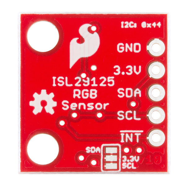
I can't tell from the back. But it looks like you have the option to pull the SCL/SDA up to 3.3V, but that it isn't the default? Is that correct? I'd have to do the math, but using the 10K board pullups to 3.3, and the arduino's internal pullups of (im not sure resistance) you could be pulling up to below the 3.63V max on the sensor and be safe without a logic level shifter.
The jumper on the back already has traces between the pads, so the I2C lines are pulled up by default (you can cut these traces if you wish to disable it). And you're correct - in general, it is safe to use 3.3V I2C parts on a 5V Arduino as long as there is a pullup to 3.3V present. (The weak-pull-ups to 5V are 20k to 50k, which in combination with the 4.7k to 3.3V leaves the high voltage at < 3.6V which is safe for the part.)
Which weak pull-ups are you referring to? The ones present by default on an Arduino? I just received this breakout board and the pull-ups appear to be labelled "0K" which doesn't make sense (usually 0-ohm resistors are labelled 0R or similar)...
Can anyone give an idea as to the distance this sensor can work effectively?
Hi, I'm a student from Brazil and I need to buy this sensor for my school project. I want to know if you export this component for Brazil? Thx
Yes, this part does not have any export restrictions. If you have any other questions please email cservice@sparkfun.com
Can I get this product without the rgb sensor. The Board should have the ADC, I2C interface and the registers. I am willing to pay the smae amount for this setup. Please do respond urgently.
Hi, unfortunately we can not sell products other than how they appear on the site. You can buy the board as is and remove the rgb sensor (although there is no ADC or registers on the board). You can also check out the Eagle files and order your own PCB from somewhere like OSH park and populate the resistors and capacitors yourself. If you have any other questions please post a new topic on the SparkFun forums.
I was just looking at the schematic of this break out board. What is the purpose of R1 (100ohm resistor in serial with VDD)? I understand this configuration is recommended on the Page 1 of the ISL29125 datasheet, but on ISL29125 Evaluation board, this resistor is omitted (Page 7 of AN1914, found on: http://www.intersil.com/content/dam/Intersil/documents/an19/an1914.pdf). Could someone give me some help? Cheers,
I couldn't find any specific reason why they would add it in their reference schematic, so without any further explanations, I'd say it's just there as a generic current limiter and very minimal ESD protection, and should be optional. ( Most of their newer style datasheets specify it, but the ISL29023 - functionally equivalent, except doesn't do RGB and is a bit more power hungry - does not )
Could anybody explain the maximum and minimum values for each Red Green and Blue reading so I can map them across colour scales, is it O - 2^16 for each colour given that their 16 bit unsigned integer readings?