- Home
- Product Categories
- XBee Boards
- SparkFun XBee Shield

SparkFun XBee Shield
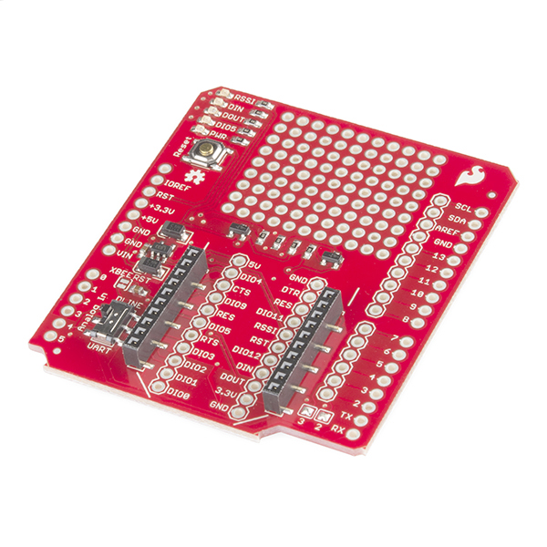
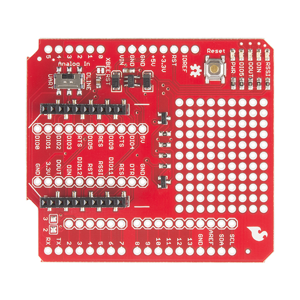
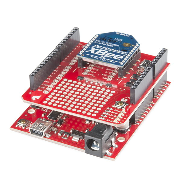
XBee radios are an awesome way to add wireless capability to your Arduino project and now it's even easier with the SparkFun XBee Shield. The shield form-factor mates directly with any dev board that has an Arduino standard footprint and equips it with wireless communication capabilities using the popular XBee module. This unit works with all XBee modules including the Series 1 and 2, standard and Pro versions.
The serial pins (DIN and DOUT) of the XBee are connected through an DPDT switch, which allows you to select a connection to either the UART pins (D0, D1) or any digital pins on the Arduino (D2 and D3 default). Power is taken from the 5V pin of the Arduino and regulated on-board to 3.3VDC before being supplied to the XBee. The shield also takes care of level shifting on the DIN and DOUT pins of the XBee. In the latest revision the diode level shifter is replaced with a more robust MOSFET level shifter.
The board also includes LEDs to indicate power and activity on DIN, DOUT, RSSI, and DIO5 pins of the XBee. The Arduino's reset button is brought out on the shield, and a 9x11 grid of 0.1" holes are available for prototyping. The shield does not come with headers installed; we recommend the Arduino Stackable Header Kit. The XBee module is also not included.
- Mounts directly onto your Arduino
- DIN and DOUT pins of XBee can be connected to either the UART pins or any digital pin on the Arduino (D2 and D3 default)
- 3.3V power regulation and MOSFET level shifting on-board
- 9x11 grid of 0.1" spaced prototyping holes
- Reset button brought out to shield
- Power, DIN, DOUT, RSSI and DIO5 indicator LEDs
- Schematic
- Eagle Files
- Hookup Guide
- GitHub (Design Files)
SparkFun XBee Shield Product Help and Resources
GPS Differential Vector Pointer
May 31, 2016
Use GPS to have two objects, a base and a target, point towards one another. This can be used to aim a directional antenna (or in the case of this project, a laser) from one object to the other object at a distance that is only limited by your ability to provide the base station with the target's GPS location.
Wireless Glove Controller
April 24, 2019
Build a wireless glove controller with Arduinos to trigger an LED using XBees!
Wireless Gesture Controlled Robot
April 25, 2019
Control the RedBot wirelessly based on the movement of your hand using an accelerometer, Arduino, and XBees!
Interactive 3D Printed LED Diamond Prop
April 19, 2018
In this tutorial, we will learn about how to create an interactive theatrical prop for a performance by 3D printing a translucent diamond prop using a non-addressable RGB LED strip and AT42QT1011 capacitive touch sensing.
Troubleshooting Tips
Having issues using this shield on your Arduino? Make sure that you check these things:
1.) Check that the XBee_Serial_Passthrough.ino file is upload to the Arduino Uno with Atmega328P
2.) Check that the switch is flipped ot the DLINE
3.) Check your connections (i.e. your solder joints)
5.) Check your power.
4.) Ensure that the settings are set to the correct configuration to send data with your XBee.
5.) If you are using an Arduino Mega, make sure to use the pins that are able to do software serial communication https://www.arduino.cc/en/Reference/SoftwareSerial.
6.) If you are using a Arduino Leonardo or any board with an Atmega32U4, make sure that you are using the correct function to send data. Serial.print() just pipes data to the Serial monitor while Serial1.print() sends data through the UART. This is explained on the product page for the Arduino Leonardo https://www.arduino.cc/en/Main/ArduinoBoardLeonardo and in this code => https://learn.sparkfun.com/tutorials/pro-micro--fio-v3-hookup-guide#example-1-blinkies
7.) If XCTU can’t find the XBee on the COM port your board is hooked up to, your operating system is probably toggling the DTR pin when it opens the COM port you selected. When the DTR pin is pulled low, the Atmega328 will reset. Therefore, while XCTU is looking for the XBee on the COM port, the Arduino is resetting and inhibiting any communication with the pass through code.
- To work around this, tie the Reset pin to the 5V pin, pulling DTR high so the the Uno doesn’t reset while XCTU looks for the XBee. (You, still need to upload the pass through code to the Uno before adding the shield and jumper wire.)
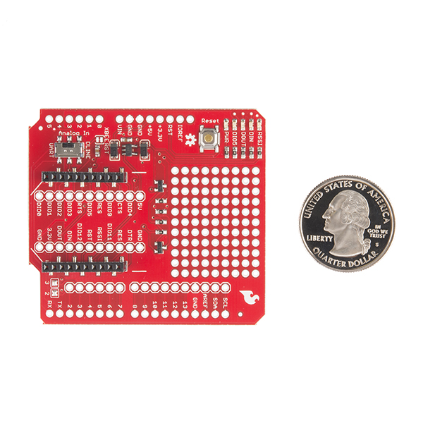
Shield Dimensions
Dimensions of the shield measured with the calipers:
width = ~53.96mm, about 2.12 in
length = ~60.26mm, about 2.37in
height = ~6.32mm, about 0.25in (measured from the bottom of the board to the top of the XBee header sockets)
This is without any header pins soldered on the shield.
Core Skill: Soldering
This skill defines how difficult the soldering is on a particular product. It might be a couple simple solder joints, or require special reflow tools.
Skill Level: Rookie - The number of pins increases, and you will have to determine polarity of components and some of the components might be a bit trickier or close together. You might need solder wick or flux.
See all skill levels
Comments
Looking for answers to technical questions?
We welcome your comments and suggestions below. However, if you are looking for solutions to technical questions please see our Technical Assistance page.
Customer Reviews
3.9 out of 5
Based on 26 ratings:
1 of 1 found this helpful:
simple to use
I was breadboarding my Xbee before getting this and also doing my logic conversions on the breadboard. This cleaned up my project and the logic converter works great. I used it on an Arduino mega and the switch to change the serial lines made this easy.
2 of 2 found this helpful:
Very simple way to get up and running quickly with Arduino and Xbee
Five minutes of soldering (don't forget to buy header pins!) and you are up and running with XBee and Arduino. The board has a switch that lets you control where the XBee's data is sent as well as a reset button. It's a simple shield that does one thing very well and then gets out of the way. Do note that it will block the ISP pins on your Arduino, however.
1 of 1 found this helpful:
Blew up in smoke
Bought two of these, soldered on headers and connected them both up to an arduino, first worked great and the second one sparked, started smoking. Both where connected identically, no solder joining two pins together or anything like that. Other then that the board seems great, only improvement I would make is include a set of stacking headers. Also thanks to the sparkfun team for resolving my issue with the faulty board, I guess with any product, good or bad, there will be the odd one or two bad ones.
It looks like the (diode?) closest to the wee switch may have blown, it appears to have a we bubble in the top of it.
Glad we could get you taken care of with a replacement!
1 of 1 found this helpful:
Perfect sheild
Perfect choice to add X Bee to an Arduino Uno . This board has everything you need and then some for future use . Clearly laid out and labeled . Simply perfect.
2 of 2 found this helpful:
works as advertized
Best option of all competition by far due to excellent documentation and tutorials.
Minor nitpick is I also find it a little annoying that it doesn't come with the headers preinstalled. even though i have headers and a soldering Iron, I would rather pay more money and have them preinstalled than spend time having to solder my own headers to it. I appreciate there is probably a good reason you don't have them installed.
1 of 1 found this helpful:
Great product
First one I bought was buggy, but customer service was great and replaced it for me. The item works great!
2 of 2 found this helpful:
Well made, works great, should come with headers
Title says it all. Excellent accessory to help make the XBee more useful, but it really should come with headers. That being said, would definitely buy again.
1 of 1 found this helpful:
Spark fun definitely stands behind their product
I bought two XBee shields,soldered on the headers, but found that one was dead on arrival. I requested a replacement and quickly received just that. Both boards work fantastically well! I've never received a faulty board before but they certainly stand behind their products. I know how rare an event such as this is, and thank them for their support. I buy most of my components from them and will continue to do just that.
1 of 1 found this helpful:
A good way to add wireless
The shield needs headers (purchased separately) and some assembly, but this was obvious from the description when I bought it. It worked perfectly and left some room on the board for the rest of my project, so it was an ideal solution for me. So much so that I've bought more of them for additional projects.
4 of 6 found this helpful:
Headers not included
Would it kill you, SparkFun, to include a set of headers with the shield? Now I got the shield only to realize that I need to order $1.50 headers, pay $5 for shipping, and wait another week before I can start using it.
Sorry, but unless the shield explicitly is listed to include headers, they generally are listed without headers. It's good to keep some extra headers in your workbench in case you need them. https://www.sparkfun.com/products/11417
1 of 3 found this helpful:
Failure to communicate
The XBee shield was mounted on an Arduino Uno. t will send data to another XBee on a PC runing XCTU but I have been unable to get data back to the Uno. have read and re-read the various tutorials about the shield and XBees but nothing I can find explains the problem. The problem lies with either the shield, the Uno or the sample sketches found in the tutorial. The shield itself is very simple so I doubt it is defective but who knows?
1 of 3 found this helpful:
Appears to work
Limited range
Range is related to your Xbee module. The shield does not have relation to range.
1 of 4 found this helpful:
Product ok, tutorials are ancient and outdated!
If you plan to use this product with wifi Xbee, don't rely on Sparkfun tutorials, they are ancient, outdated and DO NOT WORK. Go to github...
I'm sorry, but that tutorial is for series 1 xbees. It's actually not outdated or broken. But it doesn't cover Xbee WIFI. So you would want to use a different tutorial if that is your goal.
Good work, but why no level shifting for RTS to xbee?
Otherwise useful shield, with some issues:
Level shifting is only done on din / dout. If you want to use hardware flow control into xbee, RTS is NOT level shifted, so you'll have to do this yourself.
Shield should probably NOT be used on 3.3V arduinos as the level shifting will send 5V back into 3.3V microcontroller. There are cheaper shields (from iteadstudios for example) which can be configured for either 3.3V or 5V operation with a jumper.
xbee din / dout can be connected to either pins 0,1 or 2,3, which is nice, were it not for the fact that the cheaper iteadstudios shield supports connecting din/dout to any of the arduino pins.
can't stack
Would be nice to have the stacking mounting holes in this PCB. They can be drilled after the fact, but why are they not there in the first place?
Fills the need
All, in all, I'm happy with the board and would recommend it. There were a couple of small complaints, however. It came with the RxD/TxD leads from the Xbee switched to IO ports other than the Tx/Rx of the Uno I was using. It took me quite awhile poking through the documentation and the schematic to determine that was the problem. While perhaps it was "safer" to have it defaulted that way having some much more obvious documentation included would have saved me a bunch of time. I'm sure some people, when noting there was a switch on the board, would have just tried it in the other position and thereby quickly solve the problem, but I'm a careful sort and don't approach things that way.
Also, the shipping was incredibly slow. I expected ground shipping from Colorado to California to be 3 to 4 days not the 11(!) that was originally projected. It actually arrived in 10 days.
No issues - easy to mount
LED's are easily visible for debugging. After attaching headers, mount onto Arduino UNO. Move switch to DLINE and program your Arduino. Software.serial(Rx, Tx) can be used or physical Arduino Rx, Tx. Prototype area available at rear of xbee.
Tidy shield for xbee, avoids bread board jumper wires, insures 3.3V supply. Recommend for debugging and testing.
beware of conflicts
In the OLINE mode, it is expecting to 'talk' through pins 2 & 3. In my case the motor driver board is using pin 3. So, I had to cut D3's pin and add jumper from 3 to D4 (or whatever you are specifying in software for serial comm). For Mega 2560, I jumpered them to pins for Serial3, etc.
Good shield board but does not come with stackable header pins
Good board, XBee mates up well and has all the connections plus some extra prototyping area which I won't even use. It's 4 instead of 5 stars as it does not come with the stackable header pins, you need to purchase those separately, which is really a must have since this is a shield that should stack right on the Uno or Mega.
One of the best shields yet
It puts the xbee right on top where it's antenna can "see" other xbees.
There is a problem with Arduino Mega's, you need to reroute RX to pin 10, 11, 12...since pin 2 cannot support change interrupts (as per Arduino SoftwareSerial library reference). I sent an email to Sparkfun support a month ago about this problem but haven't yet been honored with a reply
0 of 3 found this helpful:
Can't get it to work yet...
Maybe my office wifi is too secure to use this...
Will update if I can get it working.
0 of 2 found this helpful:
Failure to communicate
The XBee shield was mounted on an Arduino Uno. t will send data to another XBee on a PC runing XCTU but I have been unable to get data back to the Uno. have read and re-read the various tutorials about the shield and XBees but nothing I can find explains the problem. The problem lies with either the shield, the Uno or the sample sketches found in the tutorial. The shield itself is very simple so I doubt it is defective but who knows?
XBee with an arduino
Recommend if you are using the XBee with an arduino
Great for basic, not so much for anything more
The first project I did was sensing some doors and windows, and it worked fine for that.
As I moved on to my second project, I'm running into the limitations. The Arduino analog inputs and Vin aren't brought out on the shield, just into the header. I want Vin because I want to drive an annunciator at more than 5V, and I want to use the analog inputs.
Does anyone have this working with the UART on the UNO?
using xbee-arduino and softwareserial on pins 2,3, I can successfully send AT commands to the mounted xbee s2c (802.15.4 function set) and receive correct responses. (I am in api-mode 2 because there's more that I need to do; the AT command here is just a minimal test)
However, when I have the xbee hooked up to 0,1 (with the shield switch set to UART), I am not able to get any response from the mounted xbee with the exact same code (except for Serial instead of SoftwareSerial). I am of course debugging via a bunch of attached LEDs, as I can't use the serial monitor.
My minimal sketch demonstrating this problem is here: https://gist.github.com/cpbotha/81a083e4ab4cdc6b60ef543dedbee5fd
(I have triple-checked with xctu that the xbee is setup for 9600 8n1, and I have also tried disabling flow control on the xbee (both D6 and D7))
Any help would be greatly appreciated!
If I happen to break one of the arduino headers (slc), will the rest of the shield work? (I didn't add any qwicc extensions)
Hi there, it sounds like you are looking for technical assistance. Please use the link in the banner above, to get started with posting a topic in our forums. Our technical support team will do their best to assist you. (*A picture will be helpful in understanding which pin you broke and determining if it affects the shield's functionality.)
Hi,
Is this shield compatible with the Leonardo ETH, ATmega32U4 Ethernet W5500 (V2)?
Regards.
Hi there, it sounds like you are looking for technical assistance. Please use the link in the banner above, to get started with posting a topic in our forums. Our technical support team will do their best to assist you.
That being said, you can find the schematic under the "documents tab to see what connections are used. (Don't forget to double check the pin spacing of those boards match the Uno form factor.)
I have had good luck with these boards. I think I have had one failure out of 27 I have purchased. However , you need to be aware that if your Uno, etc is already using pins 2 or 3 (e.g. motor driver board) you need to cut the pin(s) (I use a Dremel) and jumper/ reroute them to another pin(s). For example : since I'm using Serial3 on a Mega board, I rerouted X-Bee pin 2 to Mega pin 15 (Rx) and pin 3 to 14 (Tx). Also, since the headers have to be added, I printed two fixtures to hold the headers in alignment while I soldered them (I have a 3D printer). It only takes ruining a $30 motor driver board to get smarter ;)
This has been a big pain.
Digi documents refer to the sleep request pin as Pin 9. XCTU calls the sleep request pin DIO8. Sparkfun labels it on the board DTR.
Needless to say im tired of soldering/resoldering a pair of these.
How do I connect the XBee to digital pins 4 and 5 on my Uno? Pins 2 and 3 are already occupied by something else (I need them for hardware interrupts).
It works great save for one kind of important feature - there is no access to the DTR pin without having to do some work which means there is no way to save power by putting the XBee to sleep. That's sort of important for battery operated scenarios and would have been nice to see.
I can make it work, but having to do the 5V -> 3.3V conversion is a bit of a pain. Throwing an extra logic level converter on the board to connect to DTR would have been lovely. To get around that for now, I'm going to use this: https://www.sparkfun.com/products/12009 but it's turning things into a bit of a frankenstein (I also have a weather shield and a terminal block shield attached to the Uno.
Does this shield can work togheter to the USB Host Shield between two Arduinos? For instance, (Arduino+HostShield+XBeeShield+XBee) <- wireless -> (Arduino+XBeeShield+XBee). Thank you.
What is the purpose of the soldered pads 2/3 by the RX/TX lines (SJ1 & SJ3)?
What is the unsoldered pad SJ2 for labele xbee rst? I would assume it's for resetting the xbee but it's wired to the arduino reset switch and then to the xbee's DIO3 not the xBee reset pin.
Any reasoning would help greatly and thank you!
The DLINE switch is great for switching the XBee from the hardware serial lines to D2/D3. This is great if you are using D2/D3 for software serial. But what if you are not. I'm not sure if these are super popular, but for example on the Leonardo D2/D3 are the I2C lines so you probably wouldn't want to use them for software serial (although the hardware serial lines are separate from USB so you'd probably just use those anyway). Basically if you want to use something other than D2/D3 you can wire that up for your switch.
Have you ever wondered how to remotely program your Arduino using an XBee? The serial connection is easy, but what about the autoreset. The series 1 XBees have a nice feature where you can basically map an I/O pin on one to the other. If you set that up on the DTR line on the computer side this will work for autoresetting the Arduino. At some point there were a few tutorials for this and they all seemed to use DIO3 on the XBee for the reset line. Consequently you will often see boards with the option to connect DIO3 to the Arduino reset line.
Awesome! that's exactly the info I was looking for!
I am pairing this shield in a project with the Sparkfun MP3 shield which already requires use of pins D2/D3. The docs indicate I can use different digital pins if I would like. I have looked at the doc and I don’t see any examples of how to route the xbee shield to use pins other then D0/D1 (don’t want to do that way too inconvenient for programming) or D2/D3 (already used by my other sparkfun shield). What are my options on re-configuring the board to use pins D5/D10 for TX/RX. I don’t want to simply jumper D2/D3 -> D5/D10. I need D2/D3 to be left open for the other shield to use. Is that configuration possible with this shield?
When used with a Intel Galileo (Gen1) board we're having difficulty transmitting data from the Galileo to the XBee. We can receive from XBee ok. We've verified that the same shield works fine in both directions when used with a genuine Arduino Leonardo R3. We have also verified that the Intel Galileo works fine in both directions when the XBee is used with another manufacturer's shield.
Looking at signals reaching the DIN line on the XBee, we get a 3.3V (or thereabouts) level with no activity on line. When transmitting data to the XBee, the voltage alternates between 3.3 and about 1.5V (approx), not 3.3 and 0V as expected. Initially I thought that we had older boards which I know had some level conversion problems, but these are recently purchased WRL-12847. Any suggestions?
I had a look at the level converter circuit and had a hunch the 1k resistor values (R7, R8) were too low (sending too much current into the Intel Galileo UART TX pin while low). I repaced R7, R8 with 6K8 and it's working now.
when you buy this use can use stackable headers PRT-11417 you will need 1) six pin ; 2) eight pin; 1) ten pin.
please note the xbee hook up guide provides instructions for the DLINE switch actives pins 2/3 for rx/tx. This means that the uno UART serial is separate from the data to/from xbee.
also i found it good for debugging to use the tall headers on the arduino side - leaving about .25" exposed for probes or female jumpers.
had buffering problems. xbee can stream data at up to 80Kbps. Console baud rate is 9600 bps. Arduino has 64 byte buffer. Xbee radio buffers are 100 bytes in size. so some kind of flow control is needed to do more than the cute little console to console typing demo.
now switching to newSoftwareSerial(2,3) and experimenting with that.
And one more suggestion for a future revision: Instead of connecting to pin 2 and 3, connect to pin 8 and 9. This makes it easier to use the shield with AltSoftSerial, which is a lot more reliable than SoftwareSerial (and the latter doesn't care about the pins used). Also, this frees up pin 2 and 3, which are interrupt pins, so commonly used on other shields (like ethernet or wifi).
One more suggestion for a future version: The newest S2C XBee modules support being used as an SPI slave instead of using a UART. Given the lack of a free UART on most Arduinos, it would be good if there was a shield that supported this, possibly using switches or (solder) jumpers.
I tried some fiddling with jumper wires (pin 0 to 3, 1 to 2) to allow my computer to talk to the XBee module, through the USB-to-serial adapter on my Uno. This does not seem to work and I presume this is because the voltage converter on this board uses 1k pullups, while the Arduino Uno also has 1k resistors in series on the TX and RX lines (between the USB-to-serial adapter and the pin header, not between the pin header and the 328p). Together, those form a 50/50 voltage divider, breaking transmission.
Any chance that a future revision of this board could use bigger pullups to enable this trick to work?
Will this work with an Arduino that is 3.3v such as the Zero? I'm guessing the regulator would regulate the 5v out of the zero to 3.3v for the xbee but would it level shift the output of the xbee back up to 5v which could possibly damage the zero as it is a 3.3v arduino?
Is this shield compatible with the Arduino Due?
Just tried it today, it is working with the Arduino Due.
Anyone know what the diodes do on the board by the the wee switch, are they just there in case the board is incorrectly connected, what would be the implications of removing one of them?
Also, does the board only use PINS 0,1/2,3 and 5V and a ground or will there be other pins connected aswell? Also any idea which ground so I could measure total power draw of the board and xbee?
Looking at the board and the schematic I'm not seeing any diodes (other than LEDs). The board only uses 0,1,2,3, 5V, and GND. All the pins are physically connected to the Arduino so anything that is plugged into those pins should work. All GND pins are electrically connected so you should be able do any measurements on any of the pins.
They might not be diodes, they just looked that way, there just above the Dline/UART switch, there is two of them with a small 5 pin IC between them
The 5 pin IC is the voltage regulator. The part just below it is C3, and the part above is C1. These are 10uF decoupling caps on the input and output of the regulator.
I am using this shield with Arduino MEGA. I am unable to use Digital Pin 11 for PWM. Is this normal?
I would like to use a LCD and a RGB LED with this shield. I don't think it is possible.
That is not normal. The XBee shield only connects to D0 and D1 or D2 and D3. Unless you are using software serial and that is causing interference with one of the timers I'm not sure why that we be. Try removing the shield and running the code and see if you are still having problems. If so try emailing techsupport@sparkfun.com and they should be able to help.
URGENT! I have bought one of the older version of this stackable xbee shield WHICH DOES NOT HAVE SCL AND SDA PINS, I need to use them with my xbee to transmit gyroscope data wirelessly using the SCL and SDA.. HOW CAN I REVIVE THEM? (some sort of jumper wiring? how?) I am sorry i am kinda new… hope you guys help! Thanks! PLEASE!
The SCL and SDA pins are just duplicate pins. On the Uno or Redboard those pins are connected to A4 and A5. On the Leonardo they are connected to D2 and D3. You can always try just connecting to the A4 and A5 pins on the board (assuming you are using an Uno or Redboard).
Now I have another question, how should i put for the switch on the Xbee Shield, as I know the switch between UART and DLINE are actually involving pin TX-RX and D2 D3.... I think i messed up there when i was uploading codes. I got it working once when I upload the example [serial.ino] codes i got from the L3G library (Github), but I was not sure what i did with the switch. Help! :(
When you upload code to the Uno or Redboard it does so over the serial lines (RX/TX). If there is something else on those lines (even it if it isn't trying to talk) this will mess up the communication and your upload will fail. So, if your XBee is installed on the shield flip the switch to DLINE for programming to disconnect the XBee from the serial lines. For running your code it depends, if you are using hardware serial in your code flip it to UART, if you are using software serial on pins D2/D3 then flip it to DLINE.
Thanks. I should mention that I am using Leonardo actually. So I simply just added a '1' behind the "Serial" in Serial.begin and Serial.print commands in the serial.ino codes since I am trying to use Xbee to wirelessly send out data and debug on my laptop (attached with another Xbee). As such: ... Serial1.begin(9600) ... Serial1.print((int)gyro.g.x ... Does doing this means I am using hardware serial thus I am using TX RX? and is that why when i connect the gyro to D2 and D3 for SDA and SCL pins, nothing is read?
I remember that when it is working correctly, the DOUT led on the XBee shield should be indicating every Serial1.print command, right? and indeed I don't see it ever lit up.. so that is the problem? Xbee is unable to send out data. Why is that so?
So the Leonardo is much different. Unlike the ATMega328 based board it uses USB to program the board. The hardware serial pins are still in the same place, and you can still use D2/D3 for software serial, but this option isn't needed as much. Because the code is uploaded over USB though it doesn't actually matter where the switch is. The shield should not affect your ability to upload. If you are using I2C on D2 and D3 you will definitely want to keep the switch in the ULINE position so you aren't interfering with the I2C communication. As for the problem it's hard to say, your I2C might be hanging and so nothing is sent, your XBees might not be configured right, etc. Try the debugging without the XBee shield and Serial.print statements and see what shows up in the serial monitor. If you are still having problems try emailing techsupport@sparkfun.com
The description says there is a SPDT switch, but AFAICS that should be DPDT (there's two lines that are being switched, DIN and DOUT, so that's two poles).
Dimensions of the shield measured with the calipers:
This is without any header pins soldered on the shield.
Does this shield allow wireless communication between two Arduinos? For instance, (Arduino+Shield+XBee) <- wireless -> (Arduino+Shield+XBee). Thank you.
Yes, XBee provides a range of radio including ZigBee mesh networking. To learn more, check out Robert Faludi, "Building Wireless Sensor Networks", available through SparkFun here: https://www.sparkfun.com/products/10324 (also available directly through O'Reilly).
Perhaps a foolish question but I was wondering if I'd have any problems using this Xbee shield in conjunction with a libelium Xbee shield? Or is it necessary to have two shields of the same make?
If you wanted them on two different Arduinos, you shouldn't have any issue as long as you program the Arduino appropriately for the shield on it. From a quick Google search of the other shield's specs, you may need to do some pin configuration to get them both onto one Arduino. And you may run into spacing issues and RF interference between the shields. I'd recommend instead going with something like the Series 2 XBees, so you can then just create a mesh network instead of needing multiple XBees on one Arduino.
I'll take your advice then. That's about as much as I expected anyhow. Thanks for your response.
My XCTU can't discover my Xbee Module when I plugged it to my Arduino Leonardo using the exact same shield shown here. It can only detect a com port where the Leonardo is at but XCTU can't find my Xbee when it searched for that com port. Why? Helps! Urgent! Thank you all...
XCTU expects to find an XBee directly connected to the computer. It cannot talk to devices attached to Arduinos attached to the computer.
So you'll need at least two XBees, one connected to the computer (e.g. in coordinator mode), and the one attached to the Leonardo. Then the Leonardo can talk to the computer through the XBee, and XCTU will be able to detect both XBees (one through the serial port, the other through the first one's mesh network).
Hi Everyone. I have a question. Does possible to remote programming arduino via this shield and xbee seriers 1 ?
Yes.
You will need to connect DTR on your programming cable to one of the digital IO pins of the source XBee, and make sure the corresponding pin on the destination XBee is connected to the Arduino's reset pin.
The Series 2 XBees do not transmit pin levels when in AT mode, and you can't load new programs onto the Arduino in API mode.
Hi, you can buy Bluetooth 4.0 Bee which is Compatible with Xbee And Wiressless program here: http://www.elecfreaks.com/store/products_new.html
I am using this shield and configuring xBee s1 with SoftwareSerial pins 2,3. I also have a MPU9150 connected to Analog 4,5 (SDA,SCL). I am also trying to control two servos at PWM pins 9,10. I am experienced odd behavior when xBee is reading in data concerning the Servos. at a 9600 Baud rate for the xBees, I experience (every 4 seconds) an odd jerking of the servos that I cannot seem to pinpoint the issue. I have seen online that there may be an issue using SoftwareSerial in conjunction with Servos in that it may disable interrupts for a brief period of time. Is this still the case? Does anyone have successful use cases of xBee and servo configurations that I can reference and perhaps seek guidance from? Thanks!!!
Also try changing pins around. The ATMega328 has a certain number of timers. When the timer is being shared by things like software serial and servos you might get some weird thing going on. Sometimes just moving things to different a different pin that uses a different timer helps (see ATMega328 datasheet for more information about timers).
This has proven unsuccessful. Would you, you another, know that switching to use UART (pin 0,1; tx, rx) eliminate the issue? Is there an example of using the UART with this particular shield? Do I simply switch to UART on board, then eliminate the SoftSerial initialization from the code and use Serial just as I would for the console, i.e, Serial.read()? I have not tried this yet just seeking more guidance. Thanks!
I'm having trouble with this shield and the Triple Axis Accelerometer and Gyro Breakout - MPU-6050; Both use pin 2. On the bottom right corner of the shield there are two small solder-bridges labeled 3 and 2. Can i unsolder/resolder them so i can use other pins in SoftwareSerial for xBee?
just tried; worked!
now my Dout is 4 instead of 2, after i did a small wire and opened the solder-bridge.
Is there any plan to price these closer to the competitor (radioshack offers the Seeed Xbee Shield)? $24.95 (+ price of stackable headers) >> $9.99 (http://www.radioshack.com/product/index.jsp?productId=37988166)
I just assembled the headers to the shield this morning. When I use it with the Arduino Uno, Xconnect can find the radio device. I tried the XBee modules with the XBee explorer and they are recognized immediately. Tried with the UART switch in both positions; no luck. Am I missing any steps to assembling the shield?
It sounds like you are trying to connect the XBee to the computer using the Arduino Uno and the XBee shield. The Uno and shield do not make the necessary connections for this, you will want an XBee Explorer for this. If you still have questions on this feel free to email techsupport@sparkfun.com
Thank you very much for the pointer.
I was confused; the Hookup Guide on this page says we need a XBee explorer and the XBee shield to test the connections but did not give any explanation on the necessary connections.
Are there any tutorials or guides to setup the shield connections?
This XBee tutorial should be more explicit on helping you get started with connecting your XBees to a computer and configuring them to work together.
Will this shield work with zigbee module like this one? http://www.smartarduino.com/view.php?id=94121
We're not familiar with this module, but most likely. Assuming the footprint and pinout matches the XBees. The only thing the shield does is provide 3.3V power and level shift the Din and Dout pins from 5V to 3.3V. If that's what you need this should work fine.
Hi, question, is Xbee shield compatible with xbee pro s3b?, (i got XBP9B-XCST-002). When i plug to PC my arduino+xbee shield+xbee module, three leds turn on in the xbee shield (DOUT, DIO5, PWR) and when i go to XCTU and select the arduino port, it doesnt display any configuration for the RF module (wich DOES work since i can get it to work with xbee explorer). Soldering is ok, so im not sure what i could be doing wrong.
The XBee shield is compatible with the XBee Pro S3B (you may have to cut the solder jumper for the RSSI light, I don't remember which of the 900MHz modules it is that requires that). But the XBee shield does not connect the XBee module to the computer, it connects the XBee module to the Arduino. If you want to connect the XBee to the computer you want the XBee Explorer USB.
Hey - I ordered this shield in part because it brought out the I2C headers. But the two boards I received did not have them. One I had to use because it was down to short strokes but I really need those last two to come out.
Can I return one for a replacement with the newer version ? Thanks
Email techsupport@sparkfun.com with your order number. They should be able help you out with that.
what's been updated from the previous rev?
Nothing really. Most of the changes were to make the lives of our production guys easier and are things like different size components. I believe the only user noticeable difference is we've updated this to the R3 form factor so the extra 4 pins are available for your stackable headers.
Looks like this isn't compatible with the RN-XV? :(
Why not? As far as I know it should be.
From the pictures, pins 1-4 are gnd, 3.3v, data out, and data in.
on the RN-XV, pins 1-4 are 3.3v, data out, data in, and gpio 8. Gnd is on pin 10
unless I'm missing something or looking at old documentation, they don't match
EDIT: I think I found my mistake... it looks like the "first" PTH pin of GND isn't connected to the first pin in the 2mm socket, it's connected to pin 10 of the 2mm socket. I looked at the datasheet closer. :)
Yep, I don't know exactly why but we break out an extra GND pin there for you. The sockets are each 10 pins long, but there are 11 holes (you get a 5V pin as well) on each side.