- Home
- Product Categories
- ADC / DAC
- SparkFun I2C DAC Breakout - MCP4725

SparkFun I2C DAC Breakout - MCP4725
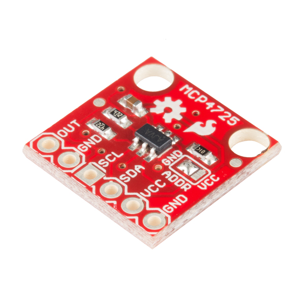
You've always wanted to output analog voltages from a microcontroller, the MCP4725 is the DAC that will let you do it! The MCP4725 is an I2C controlled Digital-to-Analog converter (DAC). A DAC allows you to send analog signal, such as a sine wave, from a digital source, such as the I2C interface on the Arduino microcontroller. Digital to analog converters are great for sound generation, musical instruments, and many other creative projects!
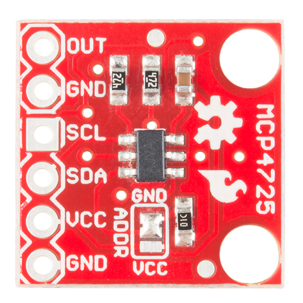
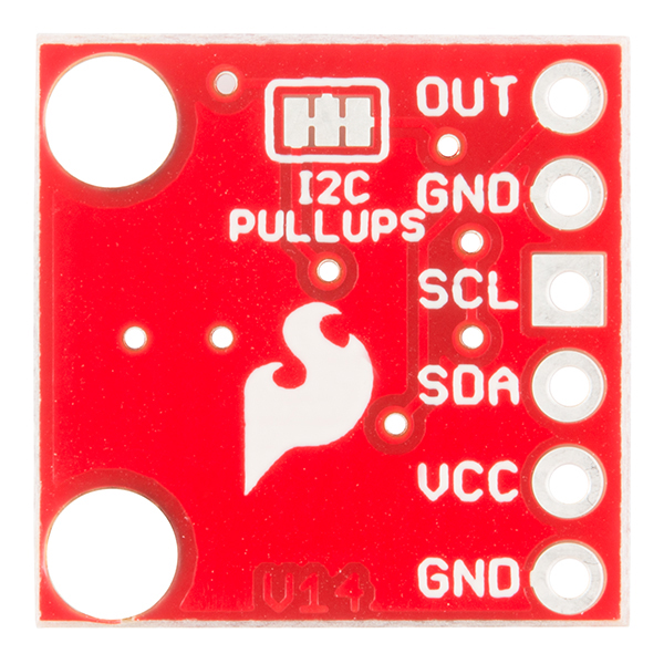
This version of the MCP4725 Breakout fixes a few issues with the board including the IC footprint, the I2C pinout, changes the overall board dimensions to better fit your projects, and a few more minor tweaks. This board breaks out each pin you will need to access and use the MCP4725 including GND and Signal OUT pins for connecting to an oscilloscope or any other device you need to hook up to the board. Also on board are SCL, SDA, VCC, and another GND for your basic I2C pinout. Additionally, if you are looking to have more than one MCP4725 on a bus, the pull-up resistors on this board can be disabled just check the Hookup Guide in the Documents section below for instructions and tips on doing this.
- 12-bit resolution
- I2C Interface (Standard, Fast, and High-Speed supported)
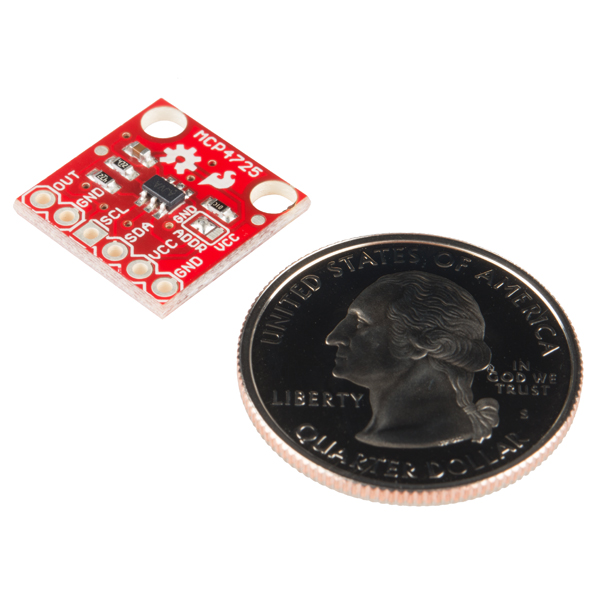
- Small package
- 2.7V to 5.5V supply
- Internal EEPROM to store settings
- Schematic
- Eagle Files
- Hookup Guide
- Datasheet (MCP4725)
- GitHub (Design Files)
SparkFun I2C DAC Breakout - MCP4725 Product Help and Resources
MIDI Shield Hookup Guide
October 8, 2015
How to assemble the SparkFun MIDI Shield, plus several example projects.
Raspberry Pi SPI and I2C Tutorial
October 29, 2015
Learn how to use serial I2C and SPI buses on your Raspberry Pi using the wiringPi I/O library for C/C++ and spidev/smbus for Python.
MCP4725 Digital to Analog Converter Hookup Guide
September 11, 2014
This is a quick hookup to help you get started with the MCP4725 DAC breakout board. This device allows you to send analog signal from a digital source, like the I2C interface on the Arduino microcontroller.
Core Skill: Soldering
This skill defines how difficult the soldering is on a particular product. It might be a couple simple solder joints, or require special reflow tools.
Skill Level: Noob - Some basic soldering is required, but it is limited to a just a few pins, basic through-hole soldering, and couple (if any) polarized components. A basic soldering iron is all you should need.
See all skill levels
Core Skill: Programming
If a board needs code or communicates somehow, you're going to need to know how to program or interface with it. The programming skill is all about communication and code.
Skill Level: Competent - The toolchain for programming is a bit more complex and will examples may not be explicitly provided for you. You will be required to have a fundamental knowledge of programming and be required to provide your own code. You may need to modify existing libraries or code to work with your specific hardware. Sensor and hardware interfaces will be SPI or I2C.
See all skill levels
Core Skill: Electrical Prototyping
If it requires power, you need to know how much, what all the pins do, and how to hook it up. You may need to reference datasheets, schematics, and know the ins and outs of electronics.
Skill Level: Rookie - You may be required to know a bit more about the component, such as orientation, or how to hook it up, in addition to power requirements. You will need to understand polarized components.
See all skill levels
Comments
Looking for answers to technical questions?
We welcome your comments and suggestions below. However, if you are looking for solutions to technical questions please see our Technical Assistance page.
Customer Reviews
4.8 out of 5
Based on 8 ratings:
1 of 1 found this helpful:
It works
I first ran the SparkFun tutorial exercise (4.5 Hz sine wave), then played with driving a micro-ammeter from the DAC--nothing very creative (yet). My write-up is here: http://lloydm.net/Demos/DAC.html
Quick breadboard accessory.
This breakout is ideal for verifying analog channels of my designs. The processor is already connected up to the motor driver assembly and something isn't going according to plan; a quick wiring job on the breadboard and the analog sensor problem is history. This breakout board is easy to hook up to troubleshoot concerns with analog inputs with great accuracy; no fuss and/or mess. I would recommend this part to folks dealing with all those analog distance sensors.
Fast Response and Accurate Output
Works well, and is easy to integrate. They included a 10k resistor to ground on the address line, so to change that bit you can just blob over all three pads and not worry about wicking away the existing bridge to GND. If this was the intent, I'd recommend removing the statement "desolder the jumper" from the Hook-up Guide.
MARVELLOUS PRODUCT
I used this DAC card MCP4725, applying communication rules defined in the Microchip datasheet. I have integrated it with a PIC16F876 20Mhtz for the management of a numeric accelerator. I am extremely happy, it worked immediately. It is a best product !!! Thank you Sparkfub !!!!
Inexpensive, works as advertised
I needed a low-cost, low speed DAC that was a step up from a PWM signal driving an RC filter. This fits the bill exactly. it is cheap, easy to program, consumes only 2 pins. The documentation has a few gaps, but it wasn't hard to get it working. Note: the documentation implies you can have more than 2 of these on an I2C bus, but given you only get control over a single address bit this seems unlikely.
Works well
The programming the output voltage was very easy and accurate.
MCP4725 Breakout Board
This works just like it is suppose too! The components selected and the options available make them easy to integrate into a prototyping environment. It certainly beats having to solder the chip to a breakout board then trying to properly place components before using. Hmm, a 10uf tantalum along with the .1uf ceramic power supply line would have been nice.
Great i2c dacs
Needed for transistor curve tracer project I am currently designing and building.
I'd like to use this to get 0-5V DAC capability for the Due. I'm controlling a device with the Due that requires 0-5V, and I can only output up to 3.3V. Will this device allow me to do I2C at 3.3V, and use the Vdd line to set the max output to 5V? Or would I need to use a logic level converter for the I2C comms?
I'm looking for the simplest way to convert an RC PWM (1-2ms range) to 0-5V. Is there a way to do it with this? If not, suggestions on how to do so? Thanks.
-------------------- Tech Support Tips/Troubleshooting/Common Issues --------------------
Pin Number Labeling with Eagle Schematic Part for the MCP4725 IC
In case anyone was wondering, the Eagle schematic part is numbered differently compared to the datasheet on page 1. There is nothing wrong with the chip or breakout board. The polarity of the IC is correct and the IC is connected to the correct application circuit.
I had been using this module successfully with a usb to i2c dongle. I am now trying one on an atmega3128p and I always get a constant voltage out. I can detect the device with the Wire library on the expected address (0x60), I can send command and get no error and I have double checked my command format multiple times. I also tried different combination of pull-up resitors. I tried with two differents Breakout MCP4725 and only one device is on the i2c bus. I am now suspecting the clock speed. I have tried to change the clock speed with: TWBR = ((F_CPU / 100000L) - 16) / 2; with no success. Any other suggestion?! I'm sure the problem is very simple, but I can't get my finger on it.
Could this be used as a stable -0.4V reference?
Any 16-bit DAC breakouts? I'm working to hack up a galvo driven 3d printer and it currently uses a 16bit DAC so I'd like to try to maintain that resolution.
The schematic shows A0 connected through R3 to ground. Shouldn't R3 actually be a pull-up to VCC, for when you want to pull A0 high? Is this an error in the schematic, or is this how the board is actually wired?
Hi, The purpose of that resistor is to prevent a direct short from Vcc to GND in the event the solder jumper is not completely cleared or is improperly soldered. A0 can be pulled straight to Vcc or GND without a resistor. It was just added as a precautionary measure.
You can get 4 of these on one i2c bus if you use two from SparkFun and two from Adafruit. Sparkfun's addresses are 0x60 and 0x61. Adafruit's are 0x62 and 0x63. This makes me very happy.
How does the i2c pullup resistor work when i'm using 2xSparkFun and 2xAdafruit MCP4725s?
Can someone confirm you only need one pull-up I2c resistor per bus? Can't tell if the Adafruit units have pull-up resistor onboard or not.
The way I2C works is that the microcontroller pulls the signal low, but if it is not pulling the signal low than the on board pull up resistor will pull it high. Different resistor values are often required for different speeds. Also keep in mind that when the microcontroller is pulling the signal to ground, VCC will be tied to this pin through the pullup resistor. You don't want the value too low and have too much power flowing through here. When you connect multiple boards will pullup resistors each of those resistors will be connected to the signal on one end and VCC on the other. This means all your resistors are in parallel. So if you had 4x 10k resistors your effective resistance is now 2.5k. Will this still work? Maybe, maybe not, it depends on the IC, the required timing etc. You definitely only need one pull-up resistor per line, in fact that is ideal. But sometimes things will still work fine if you have multiples. Also, make sure your VCCs are the same across all boards since are connecting them together.
Ooo, this may be exactly what I've been looking for for controlling my galvanometer laser scanner with my Arduino. I may have to pick up a pair at some point.
I am having an issue with my 12 bit DAC. I believe I hooked it up correctly to my ATMega2560, but I cant seem to get the expected voltage when using the Wire.write() command.
Details of my issue are [here[(http://electronics.stackexchange.com/questions/194323/arduino-with-12-bit-dac-mcp4725-not-working). Can someone help me?
Anyone has an Arduino code sample for this I2C DAC device? Thanks, Erez
You can find it in the Hookup Guide linked in the Documents section above.
Could I use this for Audio? I want to drive it from my Due using some DDS routines I've worked out. (yes, I know the Due has DAC pins, but they are sensitive and I don't want to risk blowing them out, hence an external board). I plan on sampling at 48khz so I'm fairly certain there aren't any bandwidth issues on the I2C bus. I'm just concerned about response and whether it will work for a simple audio solution (not audiophile status at all).
Is it possible to use this device in reverse, to convert an analog input to an I2C signal?
OK. Total newb question. Can someone help me figure out how to address more than one of these things from arduino? I get that I need to cut the pullup traces on all but one of the boards, but wouldn't they then still all have the same address?
As the hookup guide states, to change the address of the MCP4725, you'll need to de-solder the jumper and re-solder it in the correct configuration. By default this pin is connected to GND. So, to add a second MCP to your I2C bus, you'd need to cut the pullups and change the address jumper to be connected to Vcc on only one of your boards. The way the addressing on this IC works only allows for two devices on the same bus using the A0 pin. If you need to have more than two on the same bus, then you'll need to order the ICs directly from the manufacturer with separate addresses. See section 7.2 of the datasheet for more info on addressing.
I like the MAX522 DAC. It contains two 8-bit converters, and is SPI compatible up to 5MHz. I'm not sure if they have an SMD package, though.
Eagle Files is a 404
Sorry about that, should be fixed now.
Can I use this to power a PC fan? For instance I want to be able to use an Arduino to power a standard non-PWM fan using voltage - would this be suitable for a single fan (5-10w max) at 12V?
This outputs a varying waveform, not a constant voltage. If you need to control a 12V fan with an Arduino, I would recommend a MOSFET or a relay.
Hi JoelEB, I believe your response is misleading. This board "should" output a single voltage proportional to the value of the code that you send to it. While you "can" make it output a varying voltage, you do that by repeatedly sending it different values that will cause the voltage to vary.
Example: From the datasheet: VOUT = (VREF * Dn)/ 4096
This means that if you send it a single binary value of 4096 that it will output a steady state voltage equal to VREF.
If you send it a binary 0, then it will output a voltage of 0 volts.
The only time it will output a varying voltage is when you program a loop to "continuously" send it varying values to cause the output to vary with the desired amplitude and time scale (up to the limits of the device of course).
In a nutshell, it DOES output a constant voltage. That is what it is designed to do. That voltage is programmable and if re-programmed fast enough it can output a rather low frequency sine wave.
Hope that helps
A relay isn't what I want but the MOSFET may work. I essentially want to take the PWM signal from the Arduino and turn it into a variable voltage output to directly power the fan.
Curious, why are there separate GND pins for the VOUT and VCC?
As the hookup guide shows, those two pins are for connecting to an external device.