- Home
- Product Categories
- Arduino Shields
- RS485 Shield V2

RS485 Shield V2
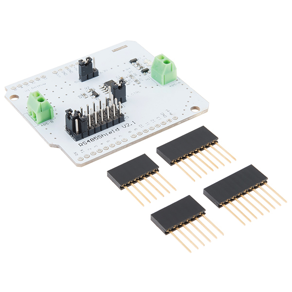
Our friends over at LinkSprite have made this nifty little RS485 Shield, now you will be able to have a communication port for your field bus directly connected to your Arduino! Even though the RS485 is sometimes thought as an "archaic" protocol, it will allow up to 32 devices to communicate through the same data line over a cable length of up to 4000ft with a maximum data rate of 10Mbit/s. Those aren't bad numbers!
This version of the RS485 shield removes the optional DB9 connector bay and adds a second 2-pin screw terminal and the ability to choose two pins from your Arduino's D0 to D7 as Software Serial Ports to communicate with the shield.
This shield does come without its headers separate so a small amount of soldering will be required before attaching it to your Arduino device.
- Schematic
- Datasheet (MAX481CSA)
- RS485 Shield V2 Tutorial
- Product Wiki
RS485 Shield V2 Product Help and Resources
Core Skill: Soldering
This skill defines how difficult the soldering is on a particular product. It might be a couple simple solder joints, or require special reflow tools.
Skill Level: Noob - Some basic soldering is required, but it is limited to a just a few pins, basic through-hole soldering, and couple (if any) polarized components. A basic soldering iron is all you should need.
See all skill levels
Core Skill: DIY
Whether it's for assembling a kit, hacking an enclosure, or creating your own parts; the DIY skill is all about knowing how to use tools and the techniques associated with them.
Skill Level: Noob - Basic assembly is required. You may need to provide your own basic tools like a screwdriver, hammer or scissors. Power tools or custom parts are not required. Instructions will be included and easy to follow. Sewing may be required, but only with included patterns.
See all skill levels
Core Skill: Electrical Prototyping
If it requires power, you need to know how much, what all the pins do, and how to hook it up. You may need to reference datasheets, schematics, and know the ins and outs of electronics.
Skill Level: Rookie - You may be required to know a bit more about the component, such as orientation, or how to hook it up, in addition to power requirements. You will need to understand polarized components.
See all skill levels
Comments
Looking for answers to technical questions?
We welcome your comments and suggestions below. However, if you are looking for solutions to technical questions please see our Technical Assistance page.
Customer Reviews
3.5 out of 5
Based on 8 ratings:
1 of 1 found this helpful:
Does not (out of the box) support Arduino Leonardo and Mega
Only 4 stars as it does not support Arduino Leonardo and Mega (and possibly others) for RX communication because apparently not all pins on these boards support change interrupts (needed for software serial if you still want to be able to program the arduino board though built in serial port on pin0/pin1) but that's not mentioned anywhere. Pins that support RX for these boards can be found here: https://www.arduino.cc/en/Tutorial/SoftwareSerialExample This RS485 shield can only use RX/TX on arduino pins 0->7 (jumpers D0-D7 on shield) and since we still want to be able to program our arduino while the shield is attached, selecting other pins as RX/TX won't work. My workaround: i placed a wire between the two RX jumpers on the shield and inserted the other end in digital port 8 on arduino (see here: https://www.dropbox.com/s/s1k1bdytmtnioy8/20170222_000743.jpg?dl=0). In software you initialize pin 8 instead of pin 6 as RX: SoftwareSerial mySerial(8,7); Probably not the best solution but it should do for now as i already got four of these...
1 of 1 found this helpful:
Did the Job with Mimimum Effort
I had to connect two Arduinos to two legacy motor controllers that used MODBUS protocol on RS485. This worked well only after a few learning pains on getting the serial settings correct (this was the fault of the motor controller not this great device). I have two of these running in the field. Using these saved me $280. over buying special RS485 to RS232 converters for the legacy motor controllers.
Up and running for ModBus to a temperature controller
I bought this to connect to a Love Controls temperature controller ModBus interface and had it up and running within less than an hour. The documentation on their website (linksprite's) leaves a little to be desired though. Lackluster documentation is the only reason I'm not giving it a five. The board is beautiful and the quality is top notch.
soldering problem
looks like cheap asian solder pads and feed throughs
Hello!
Sorry to hear about the issues with the quality of the board. Have you contacted our technical support team @ techsupport@sparkfun.com - they're usually pretty good at helping with issues like that.
needs a work around for the Mega
The Linksprite tutorial is pretty barebones member 895675 comment seems to apply to the leonardo.
1) For the Mega, yank the two jumpers going from D3-p4 and D2-p3.
2) Get two short jumper wire M-F type, plug the pin end into pin 10 on the header and the female on anyone of the P4 pins (they are bussed together)
3) Similarly jumper any of the pins on row P3 to pin 7.
4) change this code from the tutorial:
from: SoftwareSerial mySerial(3,2);
to: SoftwareSerial mySerial(10,7);
Hope this helps some folks - John B.
works great,
It works great and does exactly as i expected.
Works perfectly.
I bought this to interface an Arduino Mega to a Tescom ER3000 Pressure controller. Had a couple minor problems. The Mega doesn't supports interrupts on the digital pins this board connects to and it doesn't physically connect with the additional serial ports that Mega provides so you have to user jumper wires to connect it to the pins you want to use unless you want to use the same serial port that communicates with the serial monitor in the Arduino IDE. Not a big deal, but wasted a little time until I figured this out.
Didn't Work
I wanted to use this to make a Modbus RTU RS485 network so I bought two of them. I tried every possible jumper combination on this shield and it doesn't work. Every Modbus read (function 3) command gets check sum errors. I removed the shield and wired my Arduinio Uno TX/RX (and transmit pin 9) to a bread board with a Maxim MAX485-CPA IC and the communications work perfectly. Waste of money.
Hi, Please contact us about your issue. We may be able to help you with a return. https://www.sparkfun.com/returns
The MAX481CSA part in the provided data-sheet does not match the part number in the schematic. These two parts have different capabilities. Which is it?
LinkSprite offers no support from their end. One of my biggest peeves is products that are only "supported" by forums. What little documentation there is for this product makes no mention of the jumper settings and so far it doesn't appear to be receiving anything.
-------------------- Tech Support Tips/Troubleshooting/Common Issues --------------------
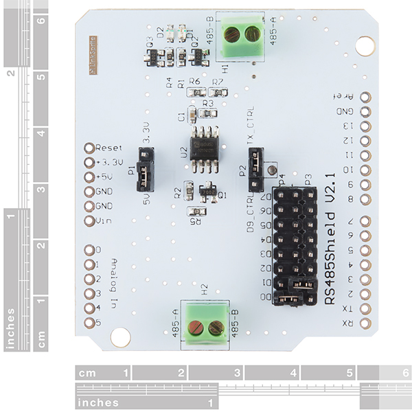
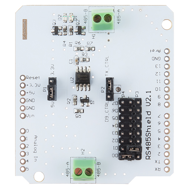
UART Pin Selection
The image shows a row of male header pins to select the UART pins. By comparing our product picture [ https://cdn.sparkfun.com//assets/parts/9/9/0/6/12965-02.jpg ] against the LinkSprite tutorial [ https://www.sparkfun.com/products/12965 ], the pins along the P4 should be connected to the Rx while P8 should be connected to Tx. You would just need to select the UART pin by moving the jumper on one side for both Rx and Tx.
Arduino Yun w/ RS485 Shield
Shields are usually designed for the Arduino Uno R3 with Atmega328P. There can be compatibility issues if you use a shield [like the RS485 V2] on a different Arduino. You would need to see if the code can compile with the board, the reserved pins the board uses, and logic levels.
Looking at the example code to use the RS485-to-serial UART converter, it is basically a serial pass through example. The code takes the converted signal and outputs it to the serial monitor. Any input received from the serial monitor will be sent back to the other side of the converter. The RS485 shield lets you choose the software serial UART or the hardware UART depending on the location of the jumper. Unfortunately, not all the pins provided on the RS485 Shield's UART selection are compatible with the Atmega32U4 on the Arduino Yun [ https://www.arduino.cc/en/Reference/SoftwareSerial ] due to its limitations:
Additionally, the hardware UART pins (pin 0 and 1) are used to communicate between the Atmega32U4 and the AR9331 [ https://www.arduino.cc/en/Main/ArduinoBoardYun ]. The logic level looks to be 5V from the Arduino Yun's specs.
Rerouting
Based on the information above, you would not be able to directly stack the RS485 V2 Shield with the Arduino Yun. However, you could reroute pins and define the software serial UART pins that are compatible for the Arduino Yun's Atmega32U4. There are many ways to reroute pins from a shield. Try looking at this Arduino.cc forum post for an example [ http://forum.arduino.cc/index.php?topic=190709.msg1461275#msg1461275 ]. The person was using a different shield but they were running into the same issue due to Atmega32U4's software serial limitation. User skr1's solution was to bend the shield pin out of place and reroute Tx and Rx to compatible software serial pins. One problem that I see is that you might not be able to stack multiple shields on the Arduino Yun if the RS485 pin is stacked in the middle level. You would probably want to have the RS485 pin stacked on the top level or use the "Go-Between Shield" [ https://www.sparkfun.com/products/11002 ].
Timing and Improvements with AltSoftSerial
User skr1 also decided to use the AltSoftSerial library [ https://www.pjrc.com/teensy/td_libs_AltSoftSerial.html ] due to some timing issues. It seems like AltSoftSerial handled serial data more efficiently with the Arduino Yun.
I'm having trouble getting this board to work for my Arduino Uno doing modbus RS485 to a water sampler, I keep getting the result code E2 (which is the timeout code I think)
i don't like this board the idea is great and RS-485 rocks. The termination resistor should have a jumper as well as the pull up and down resistor for the A and B. If you want to have 2 Arduinos talking this board would work fine as is. If you want to add more than two devices the resistors not having jumpers will cause you trouble as you add more devices. I guess you could always remove those resistors.
I've used a MAX485 chip to talk to a Mindstorm NXT before over its high speed serial line. This shield looks easier to use since there is no custom code that needs to be written (just use SoftwareSerial) and you can set what your TX/RX pins are with jumpers.