- Home
- Product Categories
- IMU
- SparkFun 9DoF IMU Breakout - LSM9DS1

SparkFun 9DoF IMU Breakout - LSM9DS1
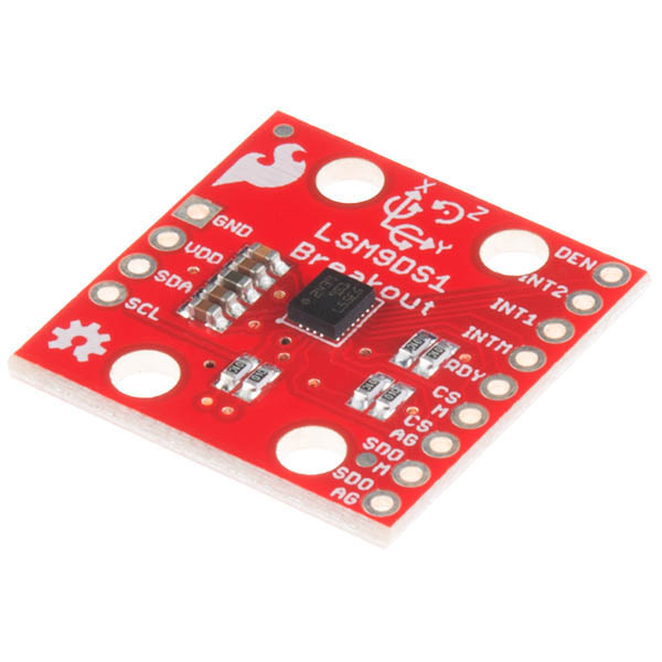
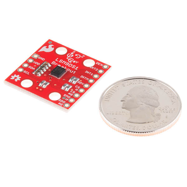
The SparkFun LSM9DS1 Breakout is a versatile, motion-sensing system-in-a-chip. It houses a 3-axis accelerometer, 3-axis gyroscope, and 3-axis magnetometer – nine degrees of freedom (9DOF) on a single board! The LSM9DS1 from STMicroelectronics is equipped with a digital interface, but even that is flexible: it supports both I2C and SPI, so you’ll be hard-pressed to find a microcontroller it doesn’t work with. This IMU-in-a-chip is so cool we put it on the quarter-sized breakout board you are currently viewing!
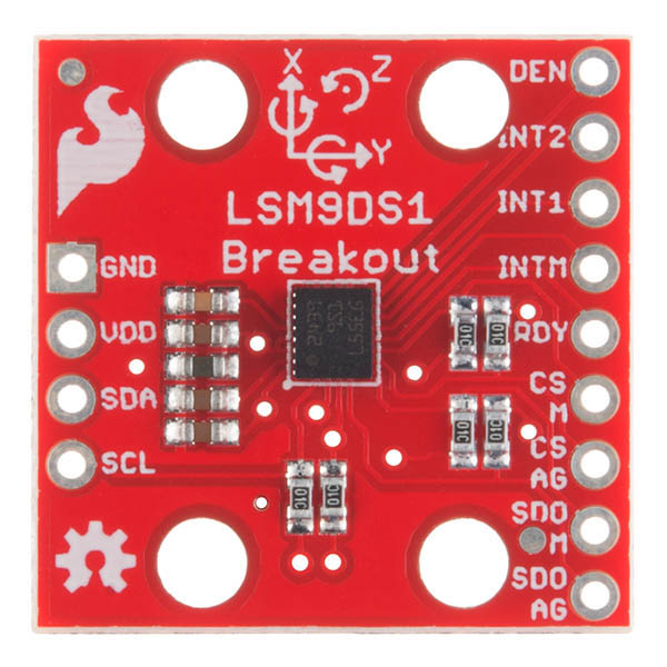
The LSM9DS1 is one of only a handful of IC’s that can measure three key properties of movement – angular velocity, acceleration, and heading – in a single IC. By measuring these three properties, you can gain a great deal of knowledge about an object’s movement and orientation. The LSM9DS1 measures each of these movement properties in three dimensions. That means it produces nine pieces of data: acceleration in x/y/z, angular rotation in x/y/z, and magnetic force in x/y/z. The LSM9DS1 Breakout has labels indicating the accelerometer and gyroscope axis orientations, which share a right-hand rule relationship with each other.
Each sensor in the LSM9DS1 supports a wide spectrum of ranges: the accelerometer’s scale can be set to ± 2, 4, 8, or 16 g, the gyroscope supports ± 245, 500, and 2000 °/s, and the magnetometer has full-scale ranges of ± 4, 8, 12, or 16 gauss.
- 3 acceleration channels, 3 angular rate channels, 3 magnetic field channels
- ±2/±4/±8/±16 g linear acceleration full scale
- ±4/±8/±12/±16 gauss magnetic full scale
- ±245/±500/±2000 dps angular rate full scale
- SPI / I2C serial interfaces
- Operating Voltage: 3.3V
- Schematic
- Eagle Files
- Hookup Guide
- Datasheet (LSM9DS1)
- GitHub (Design Files)
- GitHub (Library)
- Product Video
SparkFun 9DoF IMU Breakout - LSM9DS1 Product Help and Resources
LSM9DS1 Breakout Hookup Guide
August 13, 2015
A hookup guide for the LSM9DS1, which features a 3-axis accelerometer, 3-axis gyroscope, and 3-axis magnetometer. It's an IMU-in-a-chip!
Core Skill: Soldering
This skill defines how difficult the soldering is on a particular product. It might be a couple simple solder joints, or require special reflow tools.
Skill Level: Noob - Some basic soldering is required, but it is limited to a just a few pins, basic through-hole soldering, and couple (if any) polarized components. A basic soldering iron is all you should need.
See all skill levels
Core Skill: Programming
If a board needs code or communicates somehow, you're going to need to know how to program or interface with it. The programming skill is all about communication and code.
Skill Level: Competent - The toolchain for programming is a bit more complex and will examples may not be explicitly provided for you. You will be required to have a fundamental knowledge of programming and be required to provide your own code. You may need to modify existing libraries or code to work with your specific hardware. Sensor and hardware interfaces will be SPI or I2C.
See all skill levels
Core Skill: Electrical Prototyping
If it requires power, you need to know how much, what all the pins do, and how to hook it up. You may need to reference datasheets, schematics, and know the ins and outs of electronics.
Skill Level: Competent - You will be required to reference a datasheet or schematic to know how to use a component. Your knowledge of a datasheet will only require basic features like power requirements, pinouts, or communications type. Also, you may need a power supply that?s greater than 12V or more than 1A worth of current.
See all skill levels
Comments
Looking for answers to technical questions?
We welcome your comments and suggestions below. However, if you are looking for solutions to technical questions please see our Technical Assistance page.
Customer Reviews
4.4 out of 5
Based on 11 ratings:
3 of 3 found this helpful:
A good sensor, but needs additional support code
This is an impressive sensor, but using the Arduino code got me off on the wrong track. It is probably fine code, but I don't do much with Arduinos and I needed something running natively under Linux. I thought: Arduino, its just C++ really, just some minor porting...
Somehow I got started at the wrong end of the stick and wasted a week on this. Calibrating, reading, and making this useful without an unnecessary Arduino CPU in the picture turned frustrating. And there does not seem to be a lot of other code out there that suits my needs.
Finally, after much thrashing about, I found my way to:
https://github.com/RPi-Distro/RTIMULib.
This code, in spite of being in in a seemingly RasPi-exclusive source, builds great under Ubuntu desktop, other small arm platforms, includes both C++ and Python wrappers, and has both local and remote (serial) client tools for calibration.
The code is clear enough, and there is a useful Calibration.pdf document included that is informative. As always, however, it could use a bit of other documentation. Other versions of this library are out there, but seem to have been abandoned for now.
Native code for standard platforms makes sensors like this much more useful.
Good Product
Having used other 9 DOF IMUs, it is the available libraries that make this type of product useful, the library available for LSM9DS1 is good and examples are useful. The simple I2C setup worked with no issues for me.
It works perfect but i wish the libraries were a little better
When i first hooked this thinger up I accidentally used the DS0 vs DS1 libraries and was pretty excited because of the AHRS stuff that came in the DS0 libraries. Unfortunately those don't work with the DS1 so i had to spend an hour or so porting over the AHRS example from the DS0 libraries. Since this is a 9DOF chip it seems to be there should be an AHRS example as that is really the primary reason behind getting a chip like this, and dealing with the math intensive AHRS algorithm can be a little daunting.
Great product
Drivers integrated seamlessly. Hookup guide was very helpful
Hard to set up two or more.
The sensor works really well, but as I tried to set up together more than one, wasn't able to hook up by I2C, as the addresses can't be changed.
Works great!
Arduino library makes it really easy to use.
Poor sensor and unclear calibration
While the price is perfect, the sensor did not perform as expected. Just sitting on a table indoors, the gyro and magnetometer were bouncing wildly (~20 dps and ~3 gauss). The accelerometer was fairly stable but the point of the IMU over the accelerometer is to collect data from the other components. We bought two boards and both had this issue so we decided against using them. Wasted our money and time. If you have no need for accurate measurements, this might be fine.
Pretty slick little chip
the library and example code is pretty easy to understand and use. The i2c interface is sweet and simple. I need to figure out a few things like max update rate and such. I might update as I go.
A very interesting gadget!
This is a lot of action on a tiny board and, paired with my Arduino UNO, the project possibilities are nearly endless! I haven't tried the SPI hookup yet but the I2C is dead simple and works great. Documentation was easy to access, very complete and easy to understand. Cool is the best word!
it works!
used a redboard artemis for processor.
Is there any fusion library available which uses all the three sensors to calculate the pitch, yaw and roll with improved accuracy?
same question here.
Working AHRS Arduino code has been posted for the LSM9DS1 breakout, based on the Madgwick/Mahony filter. I also posted code for a tilt-compensated compass and detailed instructions for accurate 3D accel/magnetometer calibration.
This sensor is by far the best performer I have yet encountered, among the consumer grade IMUs.
I used the Adafruit LSM9DS1 breakout for the development as it has on board level shifters for 3V and 5V processors, but it should work perfectly with the Sparkfun breakout and a 3.3V processor.
The code requires the Sparkfun LSM9DS1 library. With default settings, the AHRS update rate is 80Hz on a 16 MHz Arduino Pro Mini.
Download at https://github.com/jremington/LSM9DS1-AHRS
Happy to entertain questions.
NOTE: The X, Y and Z accel/gyro axes DO NOT form a right handed system, as stated in the product description above. This is corrected in the code.
The X and Y magnetometers are very sensitive to mechanical stress. So the compass indication can change significantly when you secure the board to mounting pillars...
Interesting point. I never actually thought about it, but that makes sense, as most MEMS magnetometers use the hall effect to measure the magnetic field. Thanks for the tip!
Coordinate system does NOT have right-hand orientation. You have to negate readings corresponding to one of the axis to make it right-hand oriented.
Can you use this as a 3d horizon and compass with the microview?
Has anybody managed to get a meaning full heading from one of these connected to a Arduino? The example sketch seems to work well but the Heading is miles out. Does this need calibrating?
I recently purchased two of these sensors and I am looking to use them with LabView. I have been made aware that I need to break the solder connection on the back of the sensor in order to have a separate resister. Does any have ideas of exactly what needs to be done and how the resister changes. I don't have much experience with any of this.
Check out the hookup guide, but it looks like you do not have to change resistors. Right now all of the jumpers have the middle pad connected to VDD and the other pads connected through a resistor making this effectively a pullup resistor circuit. In theory you can just pull them down, but you may want to cut the traces first. I'm guessing you just need to change the address of one of them. If you still have questions feel free to email our techsupport department and they should be able to walk you through it.
just so I'm clear, this unit uses the 3 axis gyro to detect true up, vs "up" of the board/ic, correct? I'm looking for something that can identify when it's Z axis is pointed straight to the sky, vs the unit being considered "flat" in regards to initial calibration, nor it's speed in a direction (similar to gyroscope apps on the android market place) I suppose more of a rotation detection IC?
Hello, I recently purchased this breakout board and am currently designing a PCB with the LSM9DS1 on its own configured to use I2C. My 2 questions:
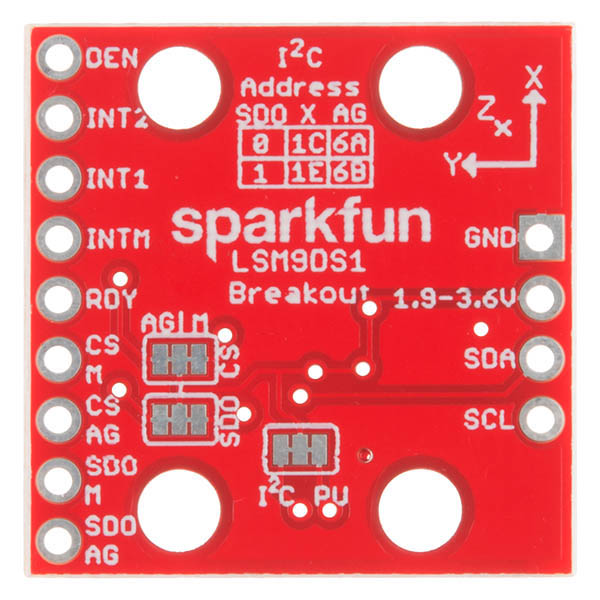
1) The LSB address select pins (SDO_A/G and SDO_M) does it matter if its configured as high or low or is this simply determining its I2C address which is used in software? What is the purpose of having this selectable?
2) I currently have the two previously mentioned pins connected to 3.3v (High) along with CS_A/G and CS_M connected to 3.3v to select I2C. Can I simply connect these pins straight to 3.3v, or do I need to put a pull-up resistor on each? Can I use my MCU's internal pull-up (20 kOhm) and not add any external ones?
(This is for the LSM9DS1 by itself, but i'm modeling the PCB based on the sparkfun breakout board).
Appreciate the help!
Looking at the schematic we do have a pullup resistor on the SDO line as it should be tied to something. There is a jumper allowing the user to disconnect the pullup and set the pin to low if they'd like. The main advantage to this is if you want to use 2 of these on one I2C bus, in that case you can change the address of one of them. In theory if you get 2 different devices that have the same I2C address you can change one as well, but this is not common.
As a general rule you should be able to connect a pin directly to VCC (instead of through a pullup) if there is no chance you will try to pull it down.
What is the ADC resolution in this thing? 16-bit?
Whenever I set the accelerometer range to 16 and calculate the magnitude of xyz it gives me ~0.67g at rest (which is obviously wrong) but when I switch the range to 8 and calculate the magnitude it gives me ~1g at rest which is correct...what's happening when I change the range to 16g?
Is this IMU compatible with ComMotion Motor Driver Shield? I tried to connect the IMU with the motor shield and the redboard but the IMU and the motor shield don't work together. Both the IMU and the motor shield works well separately. I used the I2C wiring for the IMU.
Edit: I was having issues with the module hanging.
I think the root of my problem is that I'd copied some initialization code from the example "LSM9DS1_Settings.ino". One or more of the settings was causing glitchy behaviour. After reverting to the default settings in the library's init() function, the problems went away.
Having a boatload of fun with this board. Thank you Sparkfun!
Hi, I just have 1 question. What are the differences between this IMU and the retired product LSM9DS0?
The functional differences are pretty slight. There are a few variations in the selectable sensor ranges - the LSM9DS0 offers one extra selectable accelerometer range (±6g), and the magnetometer range options differ. The DS1 has lower power capabilities, and it costs a bit less :).
thankyou
Using the LSM9DS1_Settings example I get bad readings for the temperature. I've tried dividing by 16 and adding 25 (as indicated in the data sheet - if one reads very carefully) but this doesn't solve the problem. The raw values I get are decimal -768 or -1024. Any ideas? Is there something I'm missing or is the temperature sensor on the chip bad?
Any plans for a 5V version?
you could always get a step down converter PRT-00114
Is there any difference with the LSM9DS0 besides size?
The register and device mapping are quite a bit different, but on the surface they're really, really similar.
The LSM9DS0 offers one extra selectable accelerometer range (±6g), and there are some differences in the magnetometer ranges. The DS1 has lower power capabilities though.
Enter a reply...The coordinate system for the magnetometer is different between the two devices.
The gyro and accelerometer in the LSM9DS1 have a single FIFO buffer available that stores up to 32 16-bit gyro and acceleration data values in separate registers. In the LSM9DS0 the gyro and accelerometer are located in separate sensor devices embedded within one package and have separate FIFO buffers. Practically speaking this means the code is a little different, but I'm not sure that you would notice a functional difference. For now I prefer the LSM9DS0 just because it makes it easier to debug or only use one of the sensors if you want to. The LSM9DS1 is a newer device.
Is there an AHRS firmware for this board similar to the Razor IMU?
hook up guide = 404
Live now!