- Home
- Product Categories
- Other LEDs
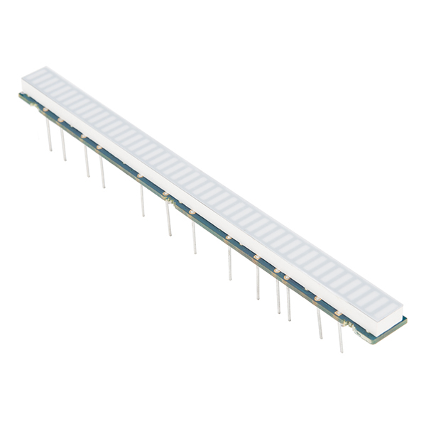
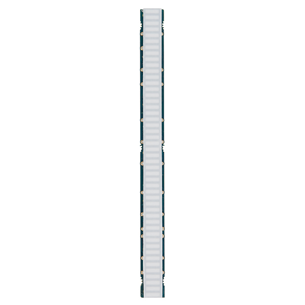
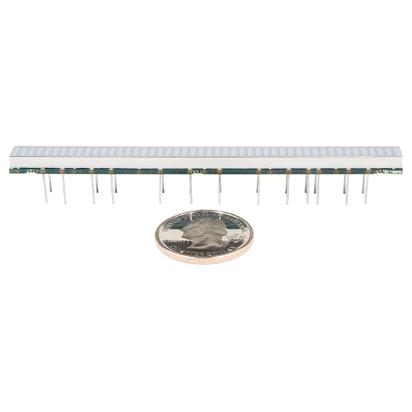
- RGB LED Bar Graph - 48 Segment

RGB LED Bar Graph - 48 Segment
This isn't your typical LED bar graph; this is a behemoth! This RGB bar graph features an impressive 48 segments of high-brightness LEDs. This common anode bar graph is perfect for projects requiring display meters with higher accuracy for reading a power charge, volume peak or signal strength. It should be mentioned that this board does not have a very compact footprint, so be sure to prepare to use a bit of space.
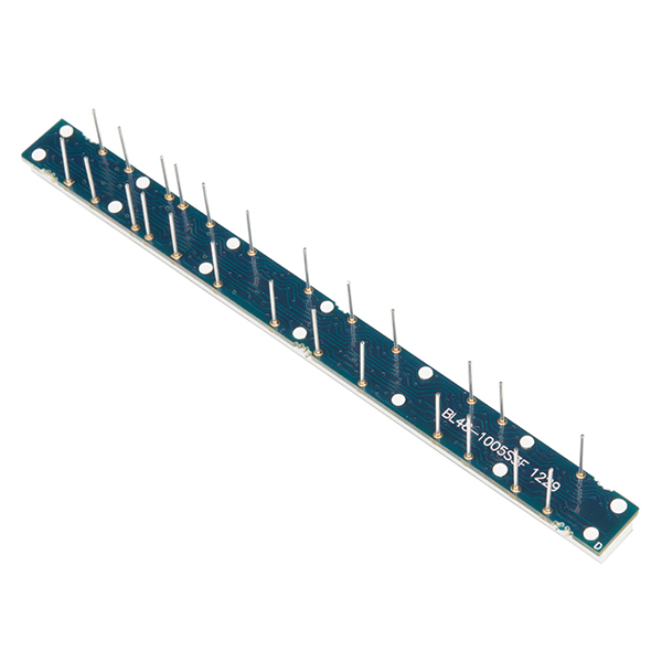
Each segment in this bar graph has an RGB LED behind it allowing each segment to be any color you’d like. This requires control of 144 LEDs. We recommend some (possibly complex) charlieplexing practices be implemented before using this part. Additionally, to help get everything set up we've added the footprint to this bar graph in our Eagle Library. Just click the Eagle icon at the top of the page.
Note: The Datasheet provided below has the blue and green color pins switched. This won't cause anything to break; just be sure to assign the colors correctly so no weirdness occurs.
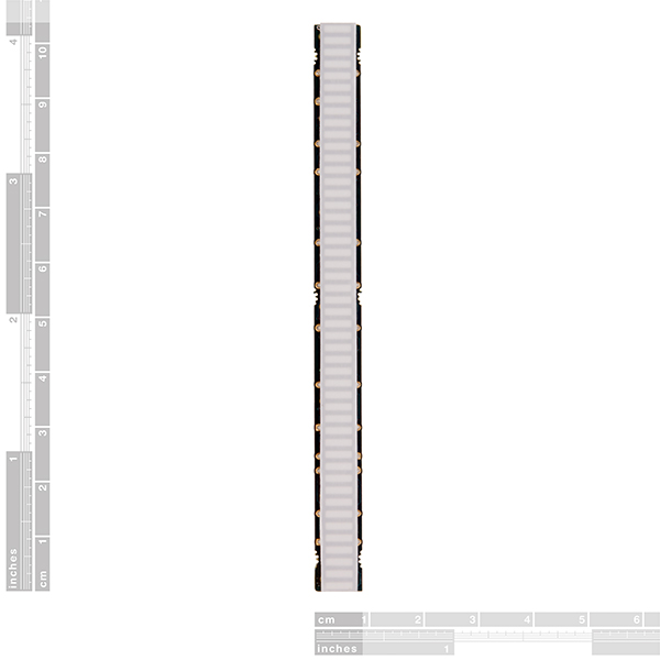
- 101mm L x 9mm W x 5mm H (w/o Headers)
- [Datasheet](https://cdn.sparkfun.com/datasheets/Components/LED/bl48-1005mfx03 1.0.pdf) (BL48-1005MFA03)
- All About LEDs
RGB LED Bar Graph - 48 Segment Product Help and Resources
Core Skill: Soldering
This skill defines how difficult the soldering is on a particular product. It might be a couple simple solder joints, or require special reflow tools.
Skill Level: Noob - Some basic soldering is required, but it is limited to a just a few pins, basic through-hole soldering, and couple (if any) polarized components. A basic soldering iron is all you should need.
See all skill levels
Core Skill: Electrical Prototyping
If it requires power, you need to know how much, what all the pins do, and how to hook it up. You may need to reference datasheets, schematics, and know the ins and outs of electronics.
Skill Level: Competent - You will be required to reference a datasheet or schematic to know how to use a component. Your knowledge of a datasheet will only require basic features like power requirements, pinouts, or communications type. Also, you may need a power supply that?s greater than 12V or more than 1A worth of current.
See all skill levels
Comments
Looking for answers to technical questions?
We welcome your comments and suggestions below. However, if you are looking for solutions to technical questions please see our Technical Assistance page.
Customer Reviews
No reviews yet.
144 LEDs? That's gross. ;)
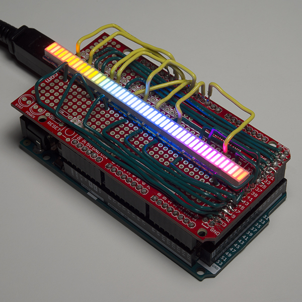
And finally a blog post showing how I chose to drive the display: http://bikerglen.com/blog/driving-a-sparkfun-48-segment-rgb-led-bar-graph/
I created a carrier board to hold the display and a driver board to drive the display. The driver board has an interface similar to that of the Sparkfun 32x32 RGB LED panels. With my boards, any hardware that can drive one of the 32x32 panels can be used to drive the 48-segment bar graph with only some small software tweaks. The Eagle schematic and board files are in my github repository: https://github.com/bikerglen/sparkfun-rgb-bar-graph
Added a photo to github too.
Charlieplexing wouldn't work well with this because of the common anode configuration. A grid matrix, yes. But not charlieplexing.
It should be possible to drive this display with a 25-output or more VFD driver. VFD drivers are push-pull so any output can source or sink.
MAX6922 and MAX6932 look like suitable devices for this use case. 16 of the outputs can source the 16 'segments', and 9 outputs can sink the RGB common channels, with current limiting resistors. The downside is that they can source 40mA but sink only 4mA per output, so the brightness wont be as high as it could be, but should be good enough for a display. Outputs can be paralleled together for higher current drive, like connect two outputs for each of the blue lines.
Could I run this with a fadecandy?
Hi there, it sounds like you are looking for technical assistance. Please use the link in the banner above, to get started with posting a topic in our forums. Our technical support team will do their best to assist you.
Sounds like a Job for the IS31FL3731
How do you drive this thing? I would like to use an Arduino Pro Mini. I would like to drive it in 3 different ways:
1) smooth transition of color from LED 1 thru 48 from let's say green to yellow to red 2) from dim to bright 3) with same brightness, just increase the number of segments ON as let's say the volume increases
I looked at the data sheet and I do not understand what C1 thru C16 is??? Do I need a multiplexer?
TIA, --Neal
Does this display contain internal current-limiting resistors or would each RGB pin need it's own resistor? It would be great if someone could create a hookup guide, potentially even showing how to use it with multiplexers/shift registers as mentioned by a few others.
You need to limit the current into each LED to 20mA, either with resistors or current limiting the source.
It's a challenge to control so we're working on a guide but we wanted to get the product live before the guide was ready because we just couldn't wait - this thing is so neat!
For 7-Segment LEDs, I've used 74HC595 as a shift register for bit shifting, and when I need to display several 7-segment LEDs, I wired several 74HC595 together in series. What would you recommend for driving 48 LEDs? I could daisy chain 6 74HC595 together, but seems kinda inefficient. What do you recommend?
This is trickier than it looks, since the LEDs are arranged in a 16x9 matrix - they have to be driven in a matrix scanned configuration. 16x9 is juuuust too big for the common matrix drive chips. To do it manually, you can use 2 74HC595's for the anodes and a 74HC238 to select the individual cathodes one at a time (+ one extra pin for the 9th one). The cathodes will need NPN or N-MOSFETs on them too, since they will be sinking up to 320mA.
The LEDs are Multiplexed, not driven individually. You need 25 bits, not 144, if I'm reading the data sheet properly.
Is this the common anode or the common cathode version?
Common Anode: BL48-1005MFA03.