- Home
- Product Categories
- Monochrome
- SparkFun 16x2 SerLCD - RGB Text (Qwiic)

SparkFun 16x2 SerLCD - RGB Text (Qwiic)
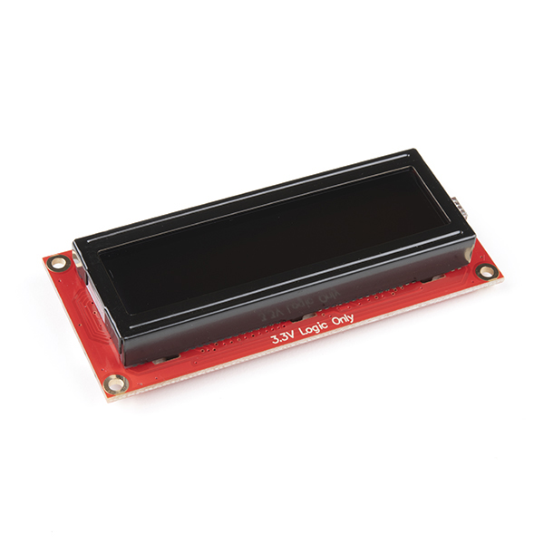
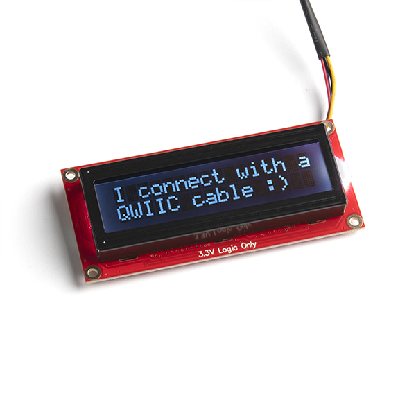
The SparkFun SerLCD is an AVR-based, serial enabled LCD that provides a simple and cost effective solution for adding a 16x2 RGB on Black Liquid Crystal Display into your project. We've seriously overhauled the PCB design on the back of the screen by including an ATmega328P that handles all of the screen control, meaning a backpack is no longer needed! This display can now communicate in three different ways: serial, I2C, and SPI. This comes equipped with a Qwiic connector, bringing serial LCDs into the Qwiic ecosystem. This simplifies the number of wires needed and allows your project to display all kinds of text and numbers.
The on-board ATmega328P AVR microcontroller utilizes 11.0592 MHz crystal for greater communication accuracy with adjustable baud rates of 1200 through 1000000 but is default set at 9600. The firmware for this SerLCD is fully opensource and allows for any customizations you may need.
Note: Since the SerLCD is a 3.3V device, please make sure you convert to 3.3V logic depending on your chosen microcontroller or single board computer. Otherwise, you may risk damaging your board.
The SparkFun Qwiic Connect System is an ecosystem of I2C sensors, actuators, shields and cables that make prototyping faster and less prone to error. All Qwiic-enabled boards use a common 1mm pitch, 4-pin JST connector. This reduces the amount of required PCB space, and polarized connections mean you can’t hook it up wrong.
Need a custom board? This component can be found in SparkFun's À La Carte board builder. You can have a custom design fabricated with this component - and your choice of hundreds of other sensors, actuators and wireless devices - delivered to you in just a few weeks.

- 16x2, RGB on Black Display
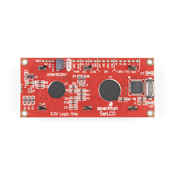
- The AVR ATMega328p (with Arduino-compatible bootloader) is populated on the back of each LCD screen and handles all of the LCD control
- Three communication options: Serial, I2C and SPI
- Adjustable I2C address controlled via software special commands (0x72 default)
- Qwiic connection
- Emergency reset to factory settings (Jumper RX to GND on bootup)
- Operational backspace character
- Incoming buffer stores up to 80 characters
- Pulse width modulation of backlight allows direct control of backlight brightness and current consumption
- Pulse width modulation of contrast allows for software defined contrast amount.
- User definable splash screen
- Open-sourced firmware and Arduino-compatible bootloader enables updates via the Arduino IDE
- Dimensions (LxWxH): 80.02x36.13x14.27mm
- Weight: 0.0779 oz.
SparkFun 16x2 SerLCD - RGB Text (Qwiic) Product Help and Resources
AVR-Based Serial Enabled LCDs Hookup Guide
August 2, 2018
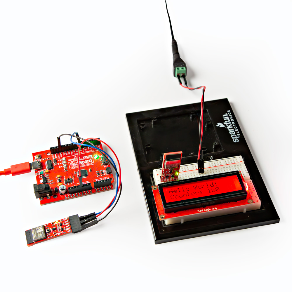
The AVR-based Qwiic Serial Enabled LCDs are a simple and cost effective solution to include in your project. These screens are based on the HD44780 controller, and include ATmega328P with an Arduino compatible bootloader. They accept control commands via Serial, SPI and I2C (via PTH headers or Qwiic connector). In this tutorial, we will show examples of a simple setup and go through each communication option.
Qwiic GPS Clock
September 14, 2020
What time is it? Time for you to... Qwiic-ly build a GPS clock and output it to a display! This project provides you with the current date and time using GPS satellites. Read the date and time as a digital or analog clock. Or even configure the clock for military, your time zone, or automatically adjust the time for daylight savings time!
Qwiic SHIM Kit for Raspberry Pi Hookup Guide
February 16, 2021
Get started with the Serial LCD with RGB backlight and 9DoF IMU (ICM-20948) via I2C using the Qwiic system and Python on a Raspberry Pi! Take sensor readings and display them in the serial terminal or SerLCD.
Core Skill: Programming
If a board needs code or communicates somehow, you're going to need to know how to program or interface with it. The programming skill is all about communication and code.
Skill Level: Rookie - You will need a better fundamental understand of what code is, and how it works. You will be using beginner-level software and development tools like Arduino. You will be dealing directly with code, but numerous examples and libraries are available. Sensors or shields will communicate with serial or TTL.
See all skill levels
Core Skill: Electrical Prototyping
If it requires power, you need to know how much, what all the pins do, and how to hook it up. You may need to reference datasheets, schematics, and know the ins and outs of electronics.
Skill Level: Rookie - You may be required to know a bit more about the component, such as orientation, or how to hook it up, in addition to power requirements. You will need to understand polarized components.
See all skill levels
Comments
Looking for answers to technical questions?
We welcome your comments and suggestions below. However, if you are looking for solutions to technical questions please see our Technical Assistance page.
Customer Reviews
3.8 out of 5
Based on 6 ratings:
2 of 2 found this helpful:
Qwiic connector poorly placed and too easy to damage
The design if Qwiic connectors is a little questionable. The female connector on the component side (the expensive piece) has four very thin metal prongs inside that are easy to mutilate if you're not careful. Typically connector designers prefer to make sure that the component side connector is more resilient because the cables are cheap to replace if damaged. The Qwiic connector on this unit is placed too close to a metal brace that impedes access. I've lost about 50% of my LCD screens to damaged Qwiic connectors so far. Be careful and @sparkfun, make sure you factor resilience into Qwiic 2 if you make an update.
Solid RGB Display
I've used the I2C and SPI interfaces with this board a few times, and it's always treated me nice. The only downside is that I had a hard time finding documentation for communicating with the board. Ultimately, I ended up code diving through a github repo, which worked well.
cool device man i was not expecting a basic arduino built onto the back
Im currently prototyping a Guitar pickup coil winder a two stage configuration phase one arduino controlled pwm setup with the 6612fng h-bridge motor controller,Success.Next Phase is SerLcd smart Lcd.I need Hall effect sensor and magnet to get motor rpm and turns count.I know i can get code and libraries to pull it off.Gonna order redboard qwiic and cables,header pins etc. to make it happen. If you can imagine you can build it. Truly yours otisonics
Fan of Qwiic system, SerLCD ok
The SerLCD works fine, but that kind of display has limited uses for me I bought it to play with the Qwiic system. My projects have serious issues with vibration and the Qwiic system gives a nice solid connection for control wires.
Very useful little LCD
Very nice product. I like the Qwiic connection, that the text color / backlight can be changed to indicate status, and that the brightness can also be changed along with the color so that it does not strain the eyes in a dark area. Much better alternative to the traditional Arduino LCDs.
A good 16x2 display
The display is easy to read. It's a good value for the price. The only negative issue was the 3.3V RX data input. Since the unit has a 9 - 3.3V raw DC power input it would be nice if the RX input could handle 5V signals. This was a not a major issue. With a handful of parts (2 diodes, 2 resistors, 1 cap) I was able to construct a data interface that worked OK.
Beware qwiic connectors on these devices. The qwiic connector itself is a little bit of a dodgy design, as the female connector which resides on the component (the expensive part, typically) has four thin flimsy pins inside that can be easily damaged. On this unit in particular, the angle and position of the socket next to a large flange make it hard to insert the male connector. Just ruined a unit trying :'(
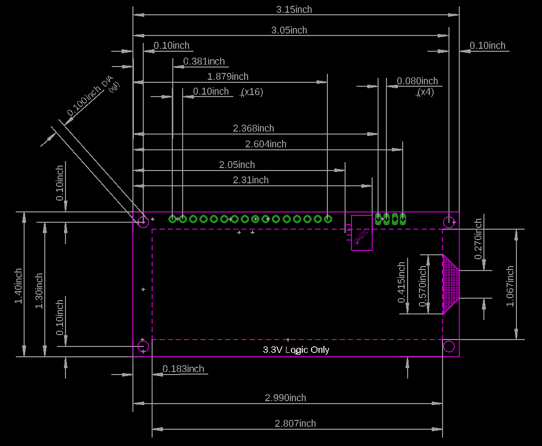
Looking for mechanical dimensions data sheet. Is one available for the new (Qwiic) SerLCD?
Hi SeeCat, We just added this to the documents tab up above. Or you can view it directly here:
Dimensional PDF
Dimensional PNG
Hope this helps and thanks for reaching out!
Please also add a dimension for the y offset from the header holes to the board edge or mounting holes. There is currently nothing referencing the locations of the header pins along the y axis.
The dimensions on these drawings appear to be incorrect. Most importantly, the 1.4" edge-to-edge dimension is off by about 0.02". Since the mounting hole locations are referenced to opposite card edges, this leads to the calculation of hole-hole distances being incorrect. If you make a footprint based off the dimensions shown in these drawings, the mounting holes will be just a little bit misaligned and you will be so mad.