- Home
- Product Categories
- GPS Boards
- SparkFun GPS Breakout - XA1110 (Qwiic)

SparkFun GPS Breakout - XA1110 (Qwiic)
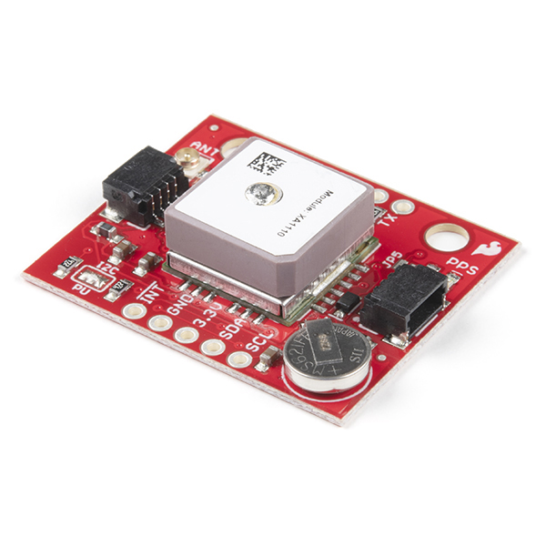
The SparkFun XA1110 GPS Breakout is a small I2C-supported module built for easy hookup, thanks to our Qwiic Connect System. Equipped with the XA1110 GPS module from GTOP, this board utilizes the MediaTek MT3333 chipset, loaded with specialized SparkFun firmware that enables both I2C and serial ports simultaneously. Using I2C means you won’t have to tie up your serial port with GPS, leaving it open to other possibilities.
This GPS Breakout supports up to 210 PRN channels with 99 search channels and 33 simultaneous tracking channels. With support of GPS, GLONASS, QZSS, SBAS and more, the onboard XA1110 can provide even more accurate positioning in multiple locations. Additionally, the XA1110 GPS Breakout is configured with an onboard RTC battery that enables a warm-start functionality, giving the X1 just five seconds to first fix, as well as a U.FL connector that provides you the option to hook up an external antenna via a U.FL cable.
Note: The I2C address of the XA1110 is 0x10 and is hardware defined. A multiplexer/Mux is required to communicate to multiple XA1110 sensors on a single bus. If you need to use more than one XA1110 sensor consider using the Qwiic Mux Breakout.
The SparkFun Qwiic Connect System is an ecosystem of I2C sensors, actuators, shields and cables that make prototyping faster and less prone to error. All Qwiic-enabled boards use a common 1mm pitch, 4-pin JST connector. This reduces the amount of required PCB space, and polarized connections mean you can’t hook it up wrong.
- 33 tracking/99 acquisition-channel GPS +GLONASS receiver
- Supports QZSS & SBAS (WAAS, EGNOS, MSAS, GAGAN)
- Sensitivity: -165dBm
- Update Rate: up to 10Hz
- 12 multi-tone active interference canceler
- 2x Qwiic connectors
- U.FL connector
- Onboard RTC battery
- Schematic
- Eagle Files
- Qwiic Landing Page
- Hookup Guide
- Datasheet (Titan X1)
- AirPrime Software User Guide
- For the modules shipped prior to June 1st, 2018 with the 'Titan X1' sticker the PMTK Packet User Manual is used
- Example Code
- Arduino Library
- Python Package
- GitHub
SparkFun GPS Breakout - XA1110 (Qwiic) Product Help and Resources
SparkFun GPS Breakout - XA1110 (Qwiic) Hookup Guide
October 19, 2017
Figure out where in the world you are with the Qwiic SparkFun GPS Breakout - XA1110.
Getting Started with the Autonomous Kit for the Sphero RVR
December 13, 2019
Want to get started in robotics? Look no further than the SparkFun autonomous kit for the Sphero RVR! Whether you purchased the Basic or Advanced kit, this tutorial will get you rolling...
Three Quick Tips About Using U.FL
December 28, 2018
Quick tips regarding how to connect, protect, and disconnect U.FL connectors.
Basic Autonomous Kit for Sphero RVR Assembly Guide
December 12, 2019
Get your Basic Autonomous Kit for Sphero RVR all hooked up with this guide!
Advanced Autonomous Kit for Sphero RVR Assembly Guide
December 12, 2019
Get your Advanced Autonomous Kit for the Sphero RVR built up with this hookup guide!
GPS Basics
December 14, 2012
The Global Positioning System (GPS) is an engineering marvel that we all have access to for a relatively low cost and no subscription fee. With the correct hardware and minimal effort, you can determine your position and time almost anywhere on the globe.
Core Skill: Programming
If a board needs code or communicates somehow, you're going to need to know how to program or interface with it. The programming skill is all about communication and code.
Skill Level: Competent - The toolchain for programming is a bit more complex and will examples may not be explicitly provided for you. You will be required to have a fundamental knowledge of programming and be required to provide your own code. You may need to modify existing libraries or code to work with your specific hardware. Sensor and hardware interfaces will be SPI or I2C.
See all skill levels
Core Skill: Electrical Prototyping
If it requires power, you need to know how much, what all the pins do, and how to hook it up. You may need to reference datasheets, schematics, and know the ins and outs of electronics.
Skill Level: Rookie - You may be required to know a bit more about the component, such as orientation, or how to hook it up, in addition to power requirements. You will need to understand polarized components.
See all skill levels
Comments
Looking for answers to technical questions?
We welcome your comments and suggestions below. However, if you are looking for solutions to technical questions please see our Technical Assistance page.
Customer Reviews
4.6 out of 5
Based on 5 ratings:
1 of 1 found this helpful:
Fantastic little breakout
I am totally pleased with this breakout. My previous GPS devices used heavier breakouts with SPI wiring. This device is so light and easy to wire up with the Qwiic system. I used it to build a model rocket flight computer that LoRa broadcasts its trajectory during flight and its GPS location on landing, all at less than 30 grams in a 34 mm diameter tube! So freakin' cool!
2 of 2 found this helpful:
Great for rocket tracking
If you are using it to track anything moving fast be sure to set it to 10hz mode. Example 5 has some code showing how to set the NMEA flags.
const uint16_t PMTK_SET_NMEA_UPDATERATE = 220; // update rate in millis. 100-10000
const uint16_t PMTK_API_SET_SBAS_ENABLED = 313; // '0'=Disable, '1'=Enable
const uint16_t PMTK_SET_NMEA_BAUDRATE = 251; // possible values are 4800,9600,14400,19200,38400,57600,115200 - must be over 57600 for 10hz
myI2CGPS.sendMTKpacket(myI2CGPS.createMTKpacket(PMTK_SET_NMEA_BAUDRATE,",115200"));
myI2CGPS.sendMTKpacket(myI2CGPS.createMTKpacket(PMTK_API_SET_SBAS_ENABLED,",0"));
myI2CGPS.sendMTKpacket(myI2CGPS.createMTKpacket(PMTK_SET_NMEA_UPDATERATE,",100"));
Works great
The ability to pull in the glonass sats really helped with a smoother speed plot and a much lower hdop! Pretty happy with this breakout! Really wish I could get an even smaller version without the Qwiic connnectors though.
GPS made Easy
Took all of 20 mins to get this unit talking to my Raspberry Pi, including soldering time. If you are familiar with NMEA format parsing the data was super simple. Even sitting in my house next to a window I was tracking up to 12 satellites.
Worked great, very fast satellite acquisition!
Acquiring satellite positions was VERY fast when under open sky, even without using a separate antenna.
I cannot get this to work with the Weather Micro Mod no matter what I do. It can "see" it and know it's plugged in, but it will not try and pick up data.
Is there an I2C MicroPython or CircuitPython implementation guide?
What is the accuracy of this chip?
Hi there, it sounds like you are looking for technical assistance. Please use the link in the banner above, to get started with posting a topic in our forums. Our technical support team will do their best to assist you.
As a note, I believe that the answer to your question can be found in the datasheet, linked under the Documents tab of this product page (just below the pricing). You should find the relevant information under the Specification section (see 2.6). (*Assuming you are referring to lateral position accuracy, it is listed at 3m.)
I am getting some strange sequences of readings coming from this GPS. For one, the update rate is quite erratic, varying from several times a second to once every few seconds without changing settings. In addition, I am getting out of order readings! See how the timestamps come in out of order below. I have hidden the rest of the sentence for security reasons.
XPS-L421X:~$ cat gpsOut.txt.final | grep GNRMC | awk -F',' '{print $1,$2}'
$GNRMC 232325.000
$GNRMC 232325.000
$GNRMC 232326.000
$GNRMC 232325.000
$GNRMC 232326.000
$GNRMC 232325.000
$GNRMC 232327.000
$GNRMC 232328.000
$GNRMC 232327.000
$GNRMC 232328.000
$GNRMC 232327.000
$GNRMC 232329.000
$GNRMC 232331.000
$GNRMC 232331.000
$GNRMC 232332.000
$GNRMC 232333.000
$GNRMC 232332.000
$GNRMC 232333.000
$GNRMC 232332.000
$GNRMC 232334.000
$GNRMC 232336.000
$GNRMC 232336.000
$GNRMC 232337.000
$GNRMC 232336.000
$GNRMC 232338.000
Is this normal for the serial port usage? I did not have anything like this issue using the Venus GPS.
We'd be happy to help you figure out the issue, please head over to our new forums to post a topic for assistance. That being said, it could be the serial buffer that is causing the data to show up out of order.
I'm not hugely happy with my board. The specs look good, but in practice, the module takes an age to download the ephemeris (cold). On a warm start (outside) it takes at least 30 seconds to get lock. And that's despite the marketing guff in the datasheet that seems to promise better.
The sensitivity is poor as well. The module I replaced with this (LS20031) used to get a fix inside no problem. With this module it really needs to be outside. So it really needs an external antenna
Boo.
Did you manage to get out of the standby mode (PMTK161,0)?
How well does this unit lock up on the satellites if you aren't using an external antenna?
We had a problem with our project that required an external antenna, these GPS modules were behaving oddly (we have 4 of them). Issuing the following command with external antenna attached:
$PGCMD,203*40
Responding with: $PGACK,GTOP_Antenna_Internal*06
Confirming our suspicions of a problem.
So the "Antenna(Active) Detect Circuit" was not doing its job, there was no insightful information in the datasheet, but looking at a sheet from a previous generation of GPS module from this company explained the it worked by detecting a current draw (>4ma) to the external antenna from the power which it supplied internally. But this pcb is supplying power to antenna through an external ferrite bead (L1) as per the reference diagram in datasheet, this makes no sense as how will the “Antenna Detector” see a current draw if power supplied externally.
So we removed L1, there was still 3.3v on the external antenna pin and with an antenna attached we now get:
$PGCMD,203*40
Responding with: $PGACK,GTOP_Antenna_External*1C
And Modules now behave properly.
The INT pin doesn't actually work with this board when reading data via I2C. It is connected properly on the PCB. Is the "specialized SparkFun firmware" to blame?
Are you sure? I'm getting the INT pin to function just fine. Keep in mind it is active low, and will pull low when NMEA data is ready to be read.
Is there a way to change the i2c address of the GPS?
Looks like a neat board
What's the accuracy in meters?
== John ==
3 Meters!