- Home
- Product Categories
- Imaging
- SparkFun Spectral Sensor Breakout - AS7262 Visible (Qwiic)

SparkFun Spectral Sensor Breakout - AS7262 Visible (Qwiic)
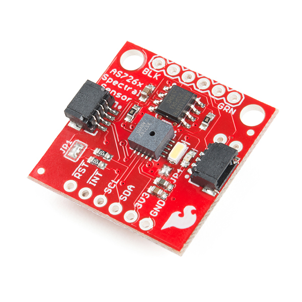
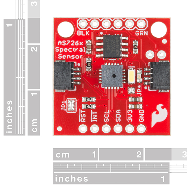
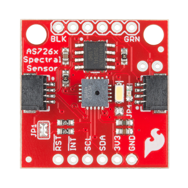
The SparkFun AS7262 Visible Spectral Sensor Breakout brings spectroscopy to the palm of your hand, making it easier than ever to measure and characterize how different materials absorb and reflect different wavelengths of light. The AS7262 Breakout is unique in its ability to communicate by both an I2C interface and serial interface using AT commands. Hookup is easy, thanks to the Qwiic connectors attached to the board --- simply plug one end of the Qwiic cable into the breakout and the other into one of the Qwiic Shields, then stack the board on a development board. You’ll be ready to upload a sketch to start taking spectroscopy measurements in no time.
The AS7262 spectrometer detects wavelengths in the visible range at 450, 500, 550, 570, 600 and 650nm of light each with 40nm of full-width half-max detection. The board also has multiple ways for you to illuminate objects that you will try to measure for a more accurate spectroscopy reading. There is an onboard LED that has been picked out specifically for this task, as well as two pins to solder your own LED into.
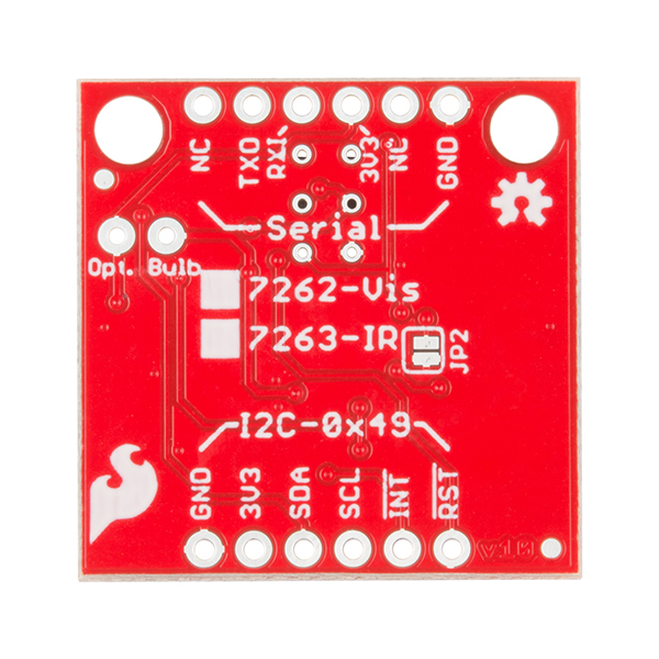
Note: The I2C address of the AS7262 is 0x49 and is hardware defined. A multiplexer/Mux is required to communicate to multiple AS7262 sensors on a single bus. If you need to use more than one AS7262 sensor consider using the Qwiic Mux Breakout.
The SparkFun Qwiic Connect System is an ecosystem of I2C sensors, actuators, shields and cables that make prototyping faster and less prone to error. All Qwiic-enabled boards use a common 1mm pitch, 4-pin JST connector. This reduces the amount of required PCB space, and polarized connections mean you can’t hook it up wrong.
- 6 visible channels: 450nm, 500nm, 550nm, 570nm, 600nm and 650nm, each with 40nm FWHM
- Visible filter set realized by silicon interference filters
- 16-bit ADC with digital access
- Programmable LED drivers
- 2.7V to 3.6V with I2C interface
- 2x Qwiic connectors
SparkFun Spectral Sensor Breakout - AS7262 Visible (Qwiic) Product Help and Resources
AS726X NIR/VIS Spectral Sensor Hookup Guide
October 19, 2017
It's now easier than ever to measure and characterize how different materials absorb and reflect different wavelengths of light. The AS726X spectral sensors allow you to detect wavelengths in the visible range (VIS) and near infrared range (NIR)!
1 of 1 found this helpful:
3.3V power only!
The flash memory on the board is only rated up to 3.6V.
Do not use a 5V UART/FTDI connector to power/communicate with the board.
Core Skill: Programming
If a board needs code or communicates somehow, you're going to need to know how to program or interface with it. The programming skill is all about communication and code.
Skill Level: Competent - The toolchain for programming is a bit more complex and will examples may not be explicitly provided for you. You will be required to have a fundamental knowledge of programming and be required to provide your own code. You may need to modify existing libraries or code to work with your specific hardware. Sensor and hardware interfaces will be SPI or I2C.
See all skill levels
Core Skill: Electrical Prototyping
If it requires power, you need to know how much, what all the pins do, and how to hook it up. You may need to reference datasheets, schematics, and know the ins and outs of electronics.
Skill Level: Rookie - You may be required to know a bit more about the component, such as orientation, or how to hook it up, in addition to power requirements. You will need to understand polarized components.
See all skill levels
Comments
Looking for answers to technical questions?
We welcome your comments and suggestions below. However, if you are looking for solutions to technical questions please see our Technical Assistance page.
Customer Reviews
4 out of 5
Based on 2 ratings:
2 of 2 found this helpful:
A nice and useful breakout board
Sparkfun and other do a great service by making breakout boards available for surface mount parts like this. I have hooked this board up to a teensy 3.2 and run the available software. The board seems to work just fine. I am in the process of building and instrument that will use this board. When that instrument is built and operating I will write a blog article on it. Until then I can't say much more than it works. BTW I also purchased the IR version of this board.
1 of 1 found this helpful:
Interesting Device - a little quirky
I set up this sensor with an STM32F103 controller. So the 1st thing you need to do is write the functions needed to communicate. There are only 4 registers - the device address, status, read, and write. That is were the quirkiness starts. To read or write you need to read and write to those registers and provide a "virtual register" address to get to the register you want. This is the only device I've seen that does this. There is some example code in the data sheet, which is helpful. If you are not using this with an Arduino you need to download the AS726X header and implementation files (.h and .ccp) from the link provided. Use these as a guide to write your functions.
I made a light table setup with a diffraction grating and lens and set the device at the focal point and moved it through the color bands. I found that I got the highest response on Orange and Green - not what I expected but on reflection that could be just the characteristic of the lamp I was using - a 60 W equivalent LED bulb (UtiliTech) I got from WalMart. I think of this as another "quirk".
Bottom line. This is an interesting device, it works fine, and I'm still learning how it behaves. If you are considering using this device, you really need to think about what the values you measure really mean and how you want to use them. This will depend on your particular setup and light source. I'd like to eventually use it as a spectrometer for measuring light being absorbed by solutions or to take elemental spectra. So I'm not sure how to take the output and use it quantitatively. Still working on that.
I am having a lot of difficulty using this to write to a uSD card using OpenLog. Maybe I can't figure it out but it seems to want to have a serial port connected to run the 'mysensor'.begin(). Without a serial port connected, it hangs up. Once a serial port is connected the data will write to the SD card fine using open log. I want to run it stand-alone so my solution so far is to get an old phone, install a serial monitor app and use it to monitor data, power everything and actually have a logging back-up by recording the serial feed.
what is the frequency response for detecting pulsed light?
what is the best distance for making the reading? thank you
Hello,
Apparently, apart from the AS7262 and AS7263, AMS also makes a AS7261. That one would be able to produce X Y Z CIE coördinates. See http://ams.com/eng/Products/Spectral-Sensing/Multi-spectral-Sensing/AS7261 . Other interesting chips are the AS7264N and AS7265 , the latter delivering even 18 sensor channels.
Would these chips be usable on the same breakout board? Has Sparkfun any intentions to produce a breakout for any of these too?
Beste regards, Marc
I just got the sensor and the SparkFun Serial Basic Breakout - CH340G. Has anyone used the Serial communication to control the sensor?
I was playing with the visible spectrum version a bit. I have connected it to an Arduino via an standard i2c 5V -> 3.3 V level shifter.
By now I am just using it for transmitted light measurements, using a warm white LED as light source, and some ROSCO color filters as objects. But you may also use it to perform measurements using solutions.
I have written an instructable on this. If you are interested, please have a look here: https://www.instructables.com/id/A-Mimimal-Six-Color-Transmitted-Light-Spectrophoto/
I've worked with a lot of spectrometers, etc. in the past. I had hopped that this would work as a spectrometer, it doesn't. The filters are only somewhat effective.
My first test involved using a UV LED. This LED only outputs light from ~290-~340nm. The AS7262 showed light coming in on all channels, including the 650nm (even though there was no green, yellow, orange or red light coming from my LED).
This is the same problem you'll experience using thin films like those used in popular PublicLabs projects (usually Rosco filters).
This is still a cool device, probably good for something. And the signal quality is pretty decent (nice ADC S/N) but the readings are by no means accurate.
How is your wiring? I can't get it to work properly. I connected the board via i2c, but the only thing i get is 'i2c error' via serial. :/
Hi. I can`t find any information about the purpose of Flash-chip and the possibility of working with AS726x without it. Could you please make it clear for me?
So I bought this an the NIR version. Both have the same I2C address? How can I use them at the same time?
EDIT: In my case, since I'm using an ESP8266, I realize now I can just wire this module to two lines, and the NIR module to another two lines. But normally I'm working with hardware that has dedicated I2C pins and this would have been a problem. Please make the addresses different! (Likely just a programming thing since I don't see pins for it?)
This looks about right for building a homebrew monitor profiler that actually yields useful results. It's not quite the 7 filters or whatever a Spyder has, but it's probably enough to find the color primaries of a screen in XYZ or LAB.
Sincere Question: Couldn't you do all this with a conventional camera module / sensor + additional signal processing? Are the advantages of this sensor just cost + easier signal processing? Seems cool, just wondering if I'm missing something...
You could not, the conventional camera sensor only has active pixel sensor's for red green and blue (Only 3 channels are necessary as these are what you need to produce an image on any RGB display, we only need this many channels for image production as the human eye only has 3 different types of cones) The AS7262 series has 6 different channels, allowing for detection of wavelengths in between red green and blue; something your average CMOS sensor is incapable of. The AS7263 senses 6 different wavelengths in the near infrared spectrum, something most cameras are not equipped for. (unless you happen to have an infrared camera) These sensors also use a silicon Interference filter as opposed to the active pixel sensors used in a CMOS sensor. This gives them a narrower band of spectral sensitivity.
In short, you wouldn't be able to accomplish the same with additional signal processing and a camera due to the fact that these sensors are able to detect twice as many different wavelengths as the traditional camera.
Thanks Englandsaurus, really appreciate the explanation. So, just for my own edification, let's say I have a pure yellow signal that I want to detect (i.e. centered right at, say, 570nm with very low bandwidth). The AS7262 would be able to pick that up loud and clear with the dectector centered on that wavelength. With a conventional RGB image sensor, however, the more "pure" that signal is, the worse the signal to noise ratio becomes, because there is less signal bleeding over into the RGB part of the spectrum for the RGB detectors to sense. Am I close? Thanks, again. Plan to buy a few of these to play around with.
Absolutely! CMOS sensors incorporate Bayer Filters to separate light into it's red green and blue components. I am unsure of the spectral range on many of these Bayer Filters, but your interpretation in the above comment is spot on. You would see some signal pop up in both red and green, but it would probably be noisy, and you'd have to account for the spectral range of each Bayer Filter (no fun) in order to correctly read your values.
Does this Board come with the preprogrammed FirmWare (for the Sensor) in the Flash-Chip or do we have to program the Flash ourselves? And what is the difference between the raw and the calibrated data? Are the calibration parameters also in the Flash and who performs the calibration, AMS, Sparkfun or the end-user?
Don't worry, Flash is pre-programmed so you won't have to muck about with all of that. Calibrated data is read from four registers on the AS726X and converting to a 32-bit float, while raw data is read from 2 separate registers. Calibration is performed by the chip using a stored correction matrix provided by AMS. Hope this helped!
Thanks, that sounds perfect. It seems, this module combined with a wide spectrum LED as a light source would be perfect for a DIY fixed wavelenghts (6 channels) small photometer for digital readout of some colorimetric water tests (after calibration curves with the corresponding standard solutions have been calculated of course). What do you think?