- Home
- Product Categories
- Distance
- SparkFun Distance Sensor Breakout - 4 Meter, VL53L1X (Qwiic)

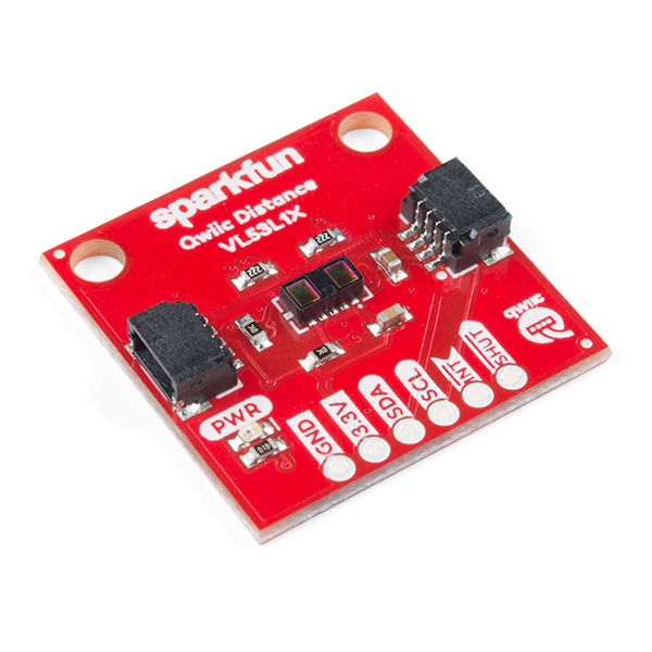
SparkFun Distance Sensor Breakout - 4 Meter, VL53L1X (Qwiic)
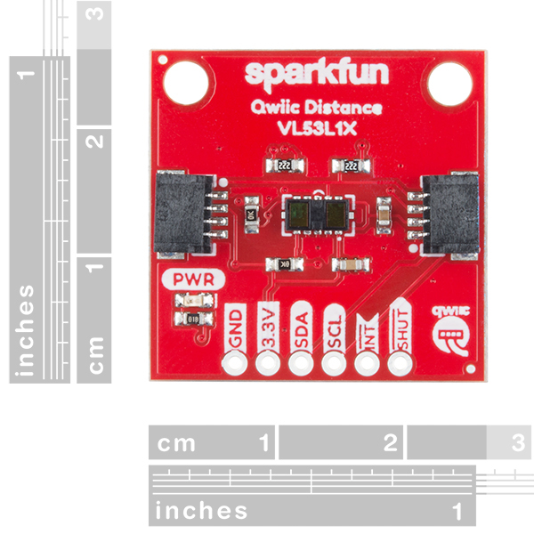
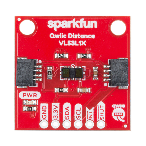
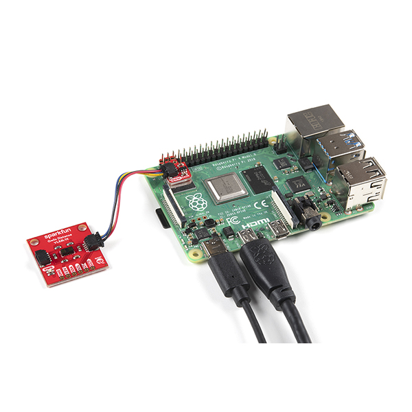
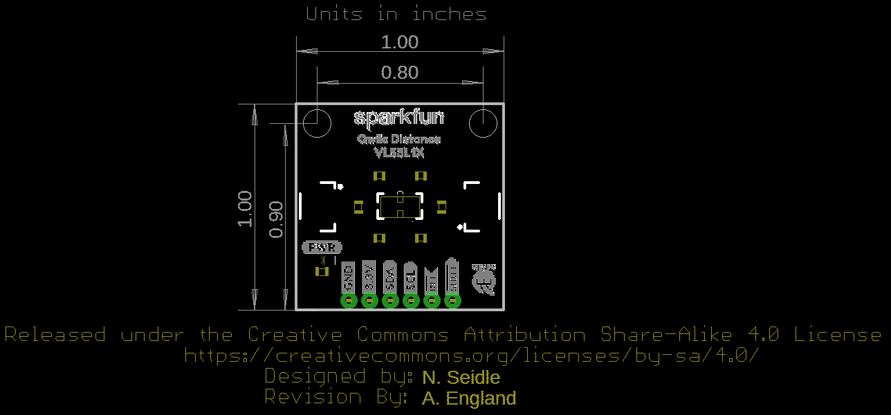
This SparkFun Distance Sensor Breakout utilizes the VL53L1X next generation ToF (Time of Flight) sensor module to give you the highly accurate measurements at long ranges for its size. The VL53L1X from STMicroelectronics uses a VCSEL (Vertical Cavity Surface Emitting Laser) to emit an Infrared laser to time the reflection to the target. That means that you will be able to measure the distance to an object from 40mm to 4m away with millimeter resolution! To make it even easier to get your readings, all communication is enacted exclusively via I2C, utilizing our handy Qwiic system so no soldering is required to connect it to the rest of your system. However, we still have broken out 0.1”-spaced pins in case you prefer to use a breadboard.
Each VL53L1X sensor features a precision to be 1mm with an accuracy around +/-5mm and a minimum read distance of this sensor is 4cm. The field of view for this little breakout is fairly narrow at 15°-27° with a read rate of up to 50Hz. Make sure to power this board appropriately since it will need 2.6V-3.5V to operate. Lastly, please be sure to remove the protective sticker on the VL53L1X before use otherwise it will, most assuredly, throw off your readings.
Note: The I2C address of the VL53L1X is 0x29 and is hardware defined. A multiplexer/Mux is required to communicate to multiple VL53L1X sensors on a single bus. If you need to use more than one VL53L1X sensor consider using the Qwiic Mux Breakout.
Note: CLASS 1 LASER PRODUCT CLASSIFIED IEC 60825-1 2014.
The SparkFun Qwiic Connect System is an ecosystem of I2C sensors, actuators, shields and cables that make prototyping faster and less prone to error. All Qwiic-enabled boards use a common 1mm pitch, 4-pin JST connector. This reduces the amount of required PCB space, and polarized connections mean you can’t hook it up wrong.
The VL53L1X Distance Sensor Breakout can also be automatically detected, scanned, configured, and logged using the OpenLog Artemis datalogger system. No programming, soldering, or setup required!
Need a custom board? This component can be found in SparkFun's À La Carte board builder. You can have a custom design fabricated with this component - and your choice of hundreds of other sensors, actuators and wireless devices - delivered to you in just a few weeks.

- Operating Voltage: 2.6V-3.5V
- Power Consumption: 20 mW @10Hz
- Measurement Range: ~40mm to 4,000mm
- Resolution: +/-1mm
- Light Source: Class 1 940nm VCSEL
- 7-bit unshifted I2C Address: 0x29
- Field of View: 15° - 27°
- Max Read Rate: 50Hz
SparkFun Distance Sensor Breakout - 4 Meter, VL53L1X (Qwiic) Product Help and Resources
Getting Started with the Autonomous Kit for the Sphero RVR
December 13, 2019
Want to get started in robotics? Look no further than the SparkFun autonomous kit for the Sphero RVR! Whether you purchased the Basic or Advanced kit, this tutorial will get you rolling...
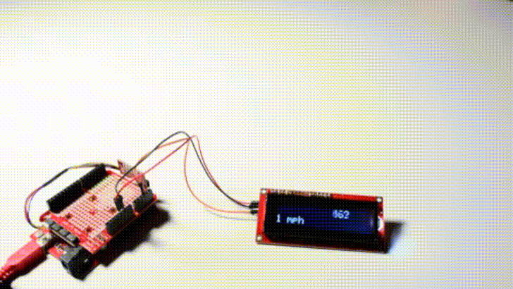
Wireless Timing Project
September 29, 2022
Time for racing, let's make a wireless timing device using ESP32 wireless communication.
Qwiic Distance Sensor (VL53L1X, VL53L4CD) Hookup Guide
February 10, 2022
The Qwiic Distance Sensor - VL53L1X is a time of flight sensor that is capable of several modes, as well as having a range of 4M. It's cousin VL53L4CD is also a time of flight sensor with similar characteristics but it has a range of about 1.3M. Let's hook it up and find out just how far away that thing over there is.
Advanced Autonomous Kit for Sphero RVR Assembly Guide
December 12, 2019
Get your Advanced Autonomous Kit for the Sphero RVR built up with this hookup guide!
Core Skill: Programming
If a board needs code or communicates somehow, you're going to need to know how to program or interface with it. The programming skill is all about communication and code.
Skill Level: Competent - The toolchain for programming is a bit more complex and will examples may not be explicitly provided for you. You will be required to have a fundamental knowledge of programming and be required to provide your own code. You may need to modify existing libraries or code to work with your specific hardware. Sensor and hardware interfaces will be SPI or I2C.
See all skill levels
Core Skill: Electrical Prototyping
If it requires power, you need to know how much, what all the pins do, and how to hook it up. You may need to reference datasheets, schematics, and know the ins and outs of electronics.
Skill Level: Rookie - You may be required to know a bit more about the component, such as orientation, or how to hook it up, in addition to power requirements. You will need to understand polarized components.
See all skill levels
Comments
Looking for answers to technical questions?
We welcome your comments and suggestions below. However, if you are looking for solutions to technical questions please see our Technical Assistance page.
Customer Reviews
4.1 out of 5
Based on 10 ratings:
2 of 2 found this helpful:
Very easy to get started with
Just plug and play. Accurately measures distances. I was able to get up to 3.8 meters with it.
2 of 3 found this helpful:
Really bad for short distances
I was looking for a distance measuring sensor using the Qwiic hardware platform for measuring distances between 40mm and 300mm for a robotic project.
I've tested the VL53L1X sensor with a "SparkFun RedBoard - Programmed with Arduino", a "SparkFun Qwiic Shield for Arduino", and the "SparkFun_VL53L1X_Arduino_Library.h" library mentioned in the "Qwiic Distance Sensor (VL53L1X) Hookup Guide".
- I can't get any reading for any distance below 125mm in either of the 3 distance modes. And at 125mm, the sensor would provide a reading of 1~2mm. So that doesn't match the advertised feature of a reading range starting from ~40mm.
- the readings are off by 125mm to 30mm between 125mm and 500mm respectively. But they are getting more accurate as the distance increases.
- and despite what is stated in the Sparkfun product description, I couldn't find any protective sticker on the VL53L1X that would explain such bad readings.
- you won't find in the Arduino library the examples # 4 and 6 and the functions for setting the intermeasurement period and to calibrate the sensor as illustrated in the hookup guide.
- the I2C address is 0x29 and not 0x52 as mentioned in the hookup guide. I was able to make it work on a micro:bit connected to a moto:bit by following the I2C programming sequences from the Arduino library.
The VL53L1X is definitively not worth the money for my application. An ultrasonic Sensor HC-SR04 does a better job for $4.
Works well
While outdoors in direct sunlight is a problem for this sensor (as I would expect) it works indoors very well. I have had extremely good luck and results in my applications.
Works well
My FIRST team wanted to use the sensor on our robot. We had trouble working with the I2C interface on the RoboRIO, but I was able to interface with an Arduino and talk to the RoboRIO over a USB interface.
Works great with Raspberry Pi and Homeassistant
Just added a new driver for Raspberry Pi 2 and 3 and Zero to be used as a Time of Flight platform for Homeassistant open source software. Please check links below.
https://github.com/josemotta/IoT.Hass.Farm
https://www.home-assistant.io/components/tof/
https://pypi.org/project/VL53L1X2/
Seems to work fine
I'm using it with a Teensy 4.0 board, works as advertised using the "SparkFun_VL53L1X" driver, no problems.
I have one question: is it possible to use two of these, on separate i2c buses? The constructor for SFEVL53L1X takes no arguments so I'm not sure how to tell the driver which i2c bus the device is on.
Fast and easy setup, extremely accurate readings.
I had a Maxbotix ultrasonic rangefinder with ADS1115 ADC on my Raspberry Pi-controlled Sphero RVR. I was able to go from opening package to working code in about ten minutes, and this device allowed me to rip out a Pi Hat prototyping board, the 3D-printed base plate, and the previous rangefinding comonents and wiring. I was able to replace it with a single laser rangefinder that is amazingly accurate. Win!
So Far, So Good
No problems encountered during limited testing.
Useful and recommendation
This sensor is very useful for its range of measurements ... the only thing to correct: the Qwiic connector didn't work on any of my three sensors ... it only works with pins 12C (SDA and SCL)
Need more info
I found the ST data sheet but I was unable to find out how to manipulate the registers in the device to, for example, change the I2C address so I could put more than one sensor on the bus. Looks like ST is keeping that info close to the vest. It does work fine as a single sensor.
Has anyone created/found a library that supports the interrupt function on this board?
Igoy,
I have it working with the interrupt but Sparkfun left two API calls that are needed for proper range interrupt functionality out of their driver. This results in many unneeded sleep / wake cycles. If I can get these API calls added into a modified library, I will share a link. Until then, we need to ask Sparkfun to look beyond the qwiic implementation and support the interrupt capabilities of these amazing devices.
Hi there, it sounds like you are looking for technical assistance. Please use the link in the banner above, to get started with posting a topic in our forums. Our technical support team will do their best to assist you.
That being said, I believe the Arduino library supports the interrupt pin; we just don't have an example as it is a Qwiic (aka I2C) based product. You'll have to adapt the Python package as it is strictly I2C only.
Excellent sensor and, yes, the qwiic connector gets you started quickly. Unfortunately, the qwiic implementation seems to get Most of the attention. There is an API call for setting the interrupt by range - that is the great news. Unfortunately, two needed APIs are left out of the library and, unlike many other sensors, you cannot write directly to the registers on the sensor like many other devices. This leaves you with a frustratingly - almost complete - driver and a tough road to figure out how to modify Sparkfun's library to add the needed calls. Of course, I have posted about this on Sparkfun's forum - but without any response.
So, like all things qwiic, easy to get started but a tough slog to realize the full potential of this amazing device.
This sensor worked very well indoors as long as you don't have any outdoor light coming in from a window. It definitely does not work outdoors, even in shade. The wavelength of natural light triggers erratic false positives with the sensor – something I found the sensor's manufacturer noted in some obscure place that I read that I'm afraid I can't find anymore.
@sparkfun Please update the description on this page to note that this sensor does not work outdoors at all, even in shade.
Is this compatible with my arduino uno or do i need to buy that Sparkfun redboard? Im also looking to use five of these sensors, how is it possible with this shield?
The SparkFun RedBoard Qwiic would be the easiest to setup with just a Qwiic cable, but you can use an Uno as well.
You will probably need a mux as the I2C address resets to the default everytime it is powered. Otherwise, you would need to reconfigure the I2C address on each sensor individually as you attached them to the I2C bus.
Having issues getting this to work consistently with a SparkFun SAMD21 LoRa Pro RF board. Best case, it will run for several seconds, then the readings will freeze. Various settings of timing budget and intermeasurement period did not make a difference. Most of the time it doesn't make it past the first library function call in the setup function.
Hi there I was trying to narrow the FoV bei changing the RoI with your library. I don't want to go as far as calling it a bug since I have no clue what your programmers intended to achieve with the specific line of code, however I seem to have found a solution. In the library you have the following fnct:
VL53L1X_ERROR VL53L1X::VL53L1X_SetROI(uint16_t X, uint16_t Y) { uint8_t OpticalCenter; VL53L1X_ERROR status = 0;
}
-> Changing the RoI to anything lower than 11 will result in no distance readings (-1). I changed the code from: ....if (X > 10 || Y > 10){ ....
to this: ....if (X > 0 || Y > 0){ ....
This leads to an optical center value being assigned and distance values will be returned.
This might help someone struggling with the same problem.
Today I try the software With a Arduino M0 (ATSAMD21G18) After loading the software the board was unusable. no connection possible. I have try it several times every time I had to program a new bootfile.
I don't know what I do wrong, using a other library (simple one) works fine.
best regards,
Rob
Greetings!
I am trying to create a traffic sensor / data-logger using sensors like this.
I want to place a sensor on one side of a street, and a piece of reflective metal on a fence opposite the sensor, that's about six-or-so meters away. I want to detect either an object closer than the fence, (usually by a factor of two), or an interruption of the beam, (in case the vehicle is a truck with non-reflective fabric sides - or has such a horrible paint-job that the beam doesn't reflect.)
This will be used out of doors, so ambient light is a serious concern.
I don't need millimeter accuracy. In fact, I was originally considering a simple IR emitter/detector sensor pair bouncing off a reflective surface. The easy-to-assemble Qwiic systems sound like an answer to my prayers without having to re-design the wheel.
Question: Which, of the many sensors you sell, would be a good fit? (Hopefully not the Garmin sensor for $150-or-so!)
Thanks!
Jim "JR"
The VL53L0X was quite disappointing in broad daylight, which was to be expected, but also under controlled office lighting conditions. The usable range, where no ambiguous triggers occurred was around 1 metre under office lighting and on late overcast afternoons and around 1,5 metres in near darkness. It helps putting a 2-3mm tube around the receptacle part of the sensor to prevent stray light from entering too soon. Also, distance varied by as much as +/- 20mm depending on colour, reflectance and porosity of the obstacle's material.
Is this new sensor, with its tiny lenses, noticeably better? Have you had a chance to compare it to the VL530X side-by-side?
How is the performance in strong ambient light outdoors? Is there any special housing that's necessary to improve the performance in such environments?
Can I measure the distance of a metal bob inside a metal tube of 4cm diameter with this module?....Will the laser bounce off the walls of the tube?
What I want to know is how this module runs on 3.3 volt? Everything in the STM documentation states 2.8 Volt with 1.8 volt I/O. As far as I can tell Sparkfun has the only VL53L1X module that runs on 3.3 volt with I/O on 3.3 volt.
Excellent question. Under Technical Specifications it indicates the operating voltage is 2.6 to 3.5V. Under 5.2 of the datasheet, Recommended Operating Conditions, it indicates there are two modes of this board, default, which is 1.8, and 2.8 mode. The absolute max of this board for supply is listed as 3.6V. This is I2C, so your communication lines pull the signal low and are driven by pull up resistors. The voltage across your pull up resistors will dictate your I/O voltage, which if you give this board 3.3V will be 3.3V, within the specifications of the manufacturer.
Hi, can it be used to measure water level? I am planning for a tidal gauge, but maybe absorption of light in water gives trouble. BR
TOF Lasers don't measure water reflections, sit something floating on the water, something that is highly reflective, shielded from outside light and baffled from 'wave noise' works fine.