- Home
- Product Categories
- AVR
- SparkFun Pi AVR Programmer HAT

SparkFun Pi AVR Programmer HAT
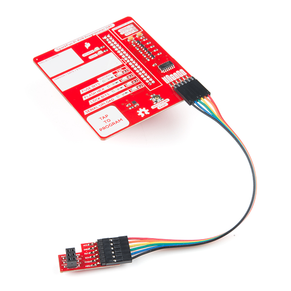
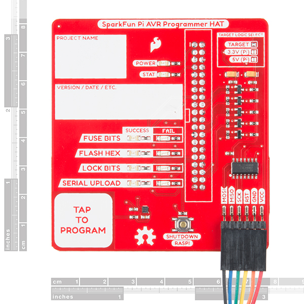
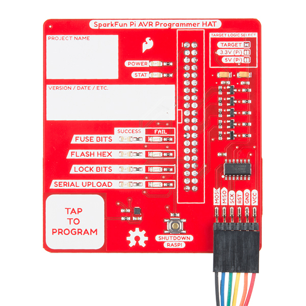
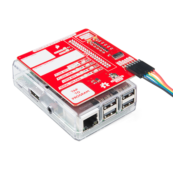
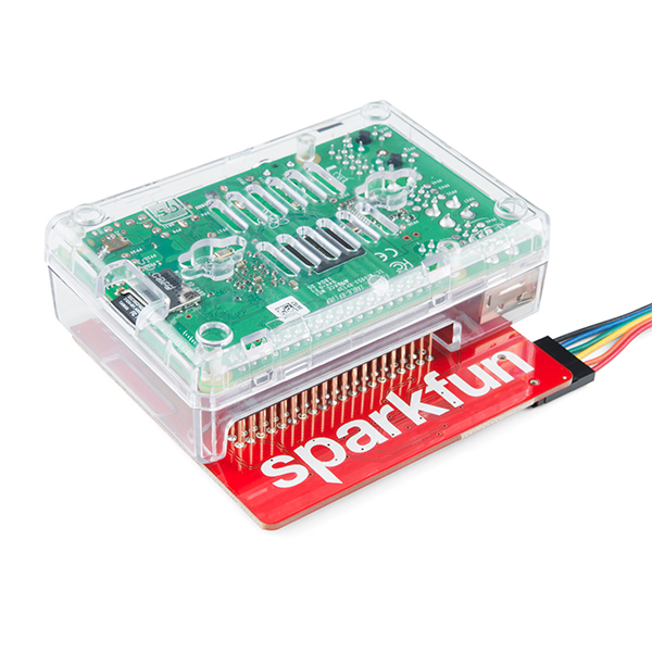
The SparkFun Pi AVR Programmer HAT makes it easy to program AVRs directly from the SPI hardware pins on any Raspberry Pi. It was originally designed as an in-house solution for SparkFun production, but now is offered as a robust programming tool for anyone to purchase! This programmer is by far one of the fastest, most reliable, and hack-able (fully open sourced) AVR programming solutions available. Whether you’re a beginner or experienced electronics enthusiast, the Pi AVR Programmer HAT should be easy to get up-and-running.
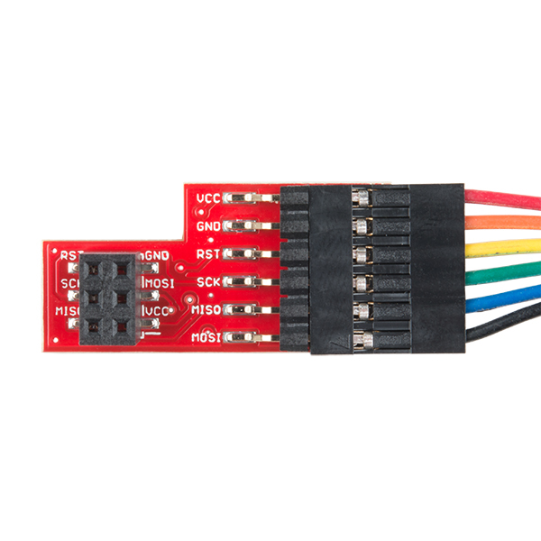
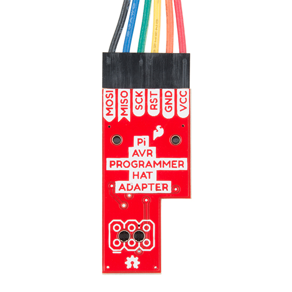
The SparkFun Pi AVR Programmer HAT plugs directly into the GPIO port on your Raspberry Pi and provides multiple unique amenities onboard including (but not limited to) a capacitive touch pad to engage programming, multiple Pass / Fail status LEDs, an isolation switch, and label boxes to keep track of your projects. Also included with each HAT is a 1x6 hookup cable that connects to the programmer's ISP header, and an ISP interface adapter equipped with a 2x3 header. Programming an AVR through an in-system programmer (ISP) can provide many benefits including a faster code upload rate, the ability to overwrite the bootloader and gain a bit more flash space, and a way to influence the fuse bits to change a multitude of settings on your target.
This HAT can be used directly from the command line using AVRDUDE commands, with some simple setup steps, or it can function as a stand-alone programmer with a capacitive touch pad engage button and status LEDs!
- 1x SparkFun Pi AVR Programmer HAT
- 1x SparkFun Pi AVR Programmer Adapter
- 1x Jumper Wire - 0.1", 6-pin, 6"
SparkFun Pi AVR Programmer HAT Product Help and Resources
Raspberry Pi Stand-Alone Programmer
March 8, 2018
This tutorial will show you how to use a headless Raspberry Pi to flash hex files onto AVR microcontrollers as a stand-alone programmer. It also tells the story about production programming challenges, how SparkFun came to this solution, and all the lessons learned along the way.
Pi AVR Programmer HAT Hookup Guide
July 26, 2018
In this tutorial, we will use a Raspberry Pi 3 and the Pi AVR Programmer HAT to program an ATMega328P target. We are going to first program the Arduino bootloader over SPI, and then upload an Arduino sketch over a USB serial COM port.
Core Skill: Programming
If a board needs code or communicates somehow, you're going to need to know how to program or interface with it. The programming skill is all about communication and code.
Skill Level: Competent - The toolchain for programming is a bit more complex and will examples may not be explicitly provided for you. You will be required to have a fundamental knowledge of programming and be required to provide your own code. You may need to modify existing libraries or code to work with your specific hardware. Sensor and hardware interfaces will be SPI or I2C.
See all skill levels
Core Skill: Electrical Prototyping
If it requires power, you need to know how much, what all the pins do, and how to hook it up. You may need to reference datasheets, schematics, and know the ins and outs of electronics.
Skill Level: Rookie - You may be required to know a bit more about the component, such as orientation, or how to hook it up, in addition to power requirements. You will need to understand polarized components.
See all skill levels
Comments
Looking for answers to technical questions?
We welcome your comments and suggestions below. However, if you are looking for solutions to technical questions please see our Technical Assistance page.
Customer Reviews
5 out of 5
Based on 2 ratings:
Awesome! Easy to setup - even for a noob.
I'm a raspi noob and had it up and running in about 10 minutes. Would have been sooner, but SPI wasn't enabled on my Raspi. Ran raspi-config, enabled SPI, and worked right away. Didn't have to reboot.
I haven't tested the logic levels and powered my Uno with a USB cord. So, I will update my review if I have trouble with the 3.3v or 5v jumpers.
Works fine
This is my new favorite way of programming! Works just fine on a Pi4 B.
First, let me say that I've met Pete Lewis (he was the "tour guide" when I visited SparkFun a few months ago). I have great respect and appreciation for his work, and that of all the folks at SparkFun!
I have more than 25 years of experience in the field of Test Engineering, ranging from "operator" in a factory (that's what got me to go back to school and get my Engineering degree) to doing both "hardware system architecture" and "system level software" on testers that sold for several million dollars apiece. (As one example, every true Intel Pentium ever made was tested on a machine I helped design.)
Based on all that experience, I have a few comments, mostly for anyone (including the folks at SparkFun) using one of these in an "industrial" setting. Please remember, this is not an "attack" on anyone -- it's just I've learned a few things in all my years of testing, and can enourage others to avoid the mistakes I've made.
My first thought is that if you use something like a Raspberry Pi 3 Model B+, you can use its WiFi capabilities to connect to your LAN (Local Area Network). By setting up a "designated directory" somewhere on a file server, it is possible to have the tester/programmer to at least verify that it's got the correct version of the code to be loaded. (Actually downloading from the server each time it's turned on is probably a bit much, but with not much programming you can do something like compare a "version_number" file locally to one on the server, and if there's a mis-match either automatically down load it or flash the lights to tell the operator that there's a potential problem.)
My next thought is that you should ALWAYS do some "datalogging". You might not need it now, but it can come in handy in the future. It is a LOT easier to log data now than to not have "historical" data in the future. This can be as simple as just writing a line to a CSV file on the aforementioned server for each device tested/programmed. It should, at a minimum, include the tester/programmer's name (and maybe a serial number for the tester/programmer), a time/date stamp, the version level of the software on the tester/programmer, the version level of software being loaded into the target, an operator ID, and a result code. It is also a very good idea to keep track of "retries", i.e., when something went wrong on the first attempt to test/program a given target and the operator decided to try it again.
I've been thinking about a way to obtain an operator ID for a "headless" tester/programmer. What I'd be inclined to go with would be a USB drive (aka a "thumb drive") with a file in it's "root" directory that contains the operator's employee number or name or some other identifying info. I did think about using the Blue Tooth capabilities of the 3 B+ to either talk to an ID chip in the badge or the operator's cell phone, but those seemed like they might be a bit flaky if there were too many people in the vicinity.
I'm also a big fan of things having a "machine readable serial number". One way that you might do this would be to designate four bytes at the end of the boot loader to be a uint_32 serial number (we can only dream of building more than 4 billion Red Boards!). The tester/programmer would have to keep track of what the last serial number used is, so that it can insert it. By the way, this could be an easy way to take care of most of the "retry" detections: the tester/programmer could try to read the serial number to see if it "makes sense" (i.e., is less than or equal to the last serial number used, and it's non-zero) -- then it's likely a "retry" unless the last attempt failed in writing the serial number.
This brings me to my one suggestion for enhancing the hardware: add a second capacitive touch pad labeled something along the lines of "retry", so the operator has a way to indicate to the tester/programmer that it's an actual retry. Although this does NOT likely make any difference on the procedure that the tester/programmer will use to test/program the target, it DOES make an important difference in the datalogging.
You could, of course, use Ethernet to connect any of the tester/programmers to the LAN, but this makes for yet another cable to hook up and clutter the work area.
There is a lot of important information to be had from analysing the aforementioned data: First, it can quickly alert you that there might be problems when you have too high a failure rate on testing/programming. Second, a good idea can be had of how much labor you can expect to expend to test/program a planned production run. Another thing that can be done, if the devices are serialized, is that if a failing device is returned from a customer, the exact lot can be identified, and if there are several in the same lot, you may be able to say "XYZ sent us a bad batch of XXX parts".
Obviously, if you're just tinkering with this on your own "bench", or using it, say, in a school lab, you can ignore all my comments!
Hey 773, Thank you for your comment! I appreciate your kind words, constructive criticisms, and ideas for solutions! I do not perceive them as "attacks" in any way.
I agree that data logging is very important, and I look forward to pursuing this further. We've always relied on a more manual recording of problems (in our own internal data system), but it is far from perfect, and it only records the problems that a technician or test developer actually records. I have integrated some data logging systems in the past for a different product that required calibration and we needed a very large sample set (the capacitive touch potentiometer). But that system actually just logged to an uSD card using an openlog on the test fixture and required manually pulling the card to retrieve the data. Not ideal, I know, but it got us through those initial builds and we were ultimately able to fine tuned the default settings.
Putting a serial number into the bootloader hex of every Redboard (and other AVR products) would, indeed, be pretty awesome. We've struggled with adding some sort of unique data to products in the past. Ultimately, we now have the "batch ID" printed on a sticker, so if there is an issue, we can at least track down the other customers that may have received a bad product. But honestly, that is a pretty rare thing around here, and the functional test fixtures do a pretty darn good job of catching issues before it leaves production. But as we grow, and see larger and larger orders, those strange little errors can lead to very big problems.
That reminds me, one time we did a huge run of the microviews and during a firmware update, the bootloader was actually not included in the "combined hex", and then it still passed testing. That was a tough lesson. I can't remember the exact number of units that went out bad, but I think it was in the thousands. It was a flaw in our process at the time that led to that disaster, and now we require third party double-checking on any firmware updates.
So thanks again, and I will definitely keep you posted. Automated data logging would be an amazing next step for our testing tools! And, as always, please don't hesitate to comment your thoughts about products and especially testing - we love it!