- Home
- Product Categories
- Encoders
- SparkFun Qwiic Twist - RGB Rotary Encoder Breakout

SparkFun Qwiic Twist - RGB Rotary Encoder Breakout
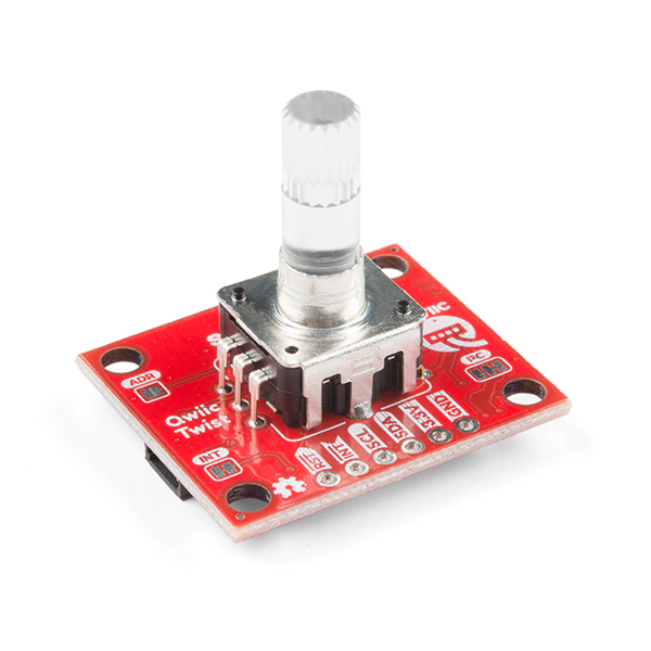
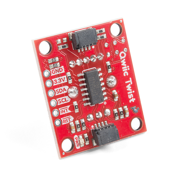
The SparkFun Qwiic Twist is a digital RGB rotary encoder breakout that is also able to connect to our Qwiic Connect System. The Twist takes care of all the various interrupts, switches, PWM'ing of LEDs, and presents all those features over an easy-to-use I2C interface. The Qwiic Twist was designed to get rid of the large mass of wires that are needed to implement an RGB encoder in a breadboard enabling you to stop messing around with interrupt debugging and get back to your project! Utilizing our handy Qwiic system, no soldering is required to connect it to the rest of your system. However, we still have broken out 0.1"-spaced pins in case you prefer to use a breadboard.
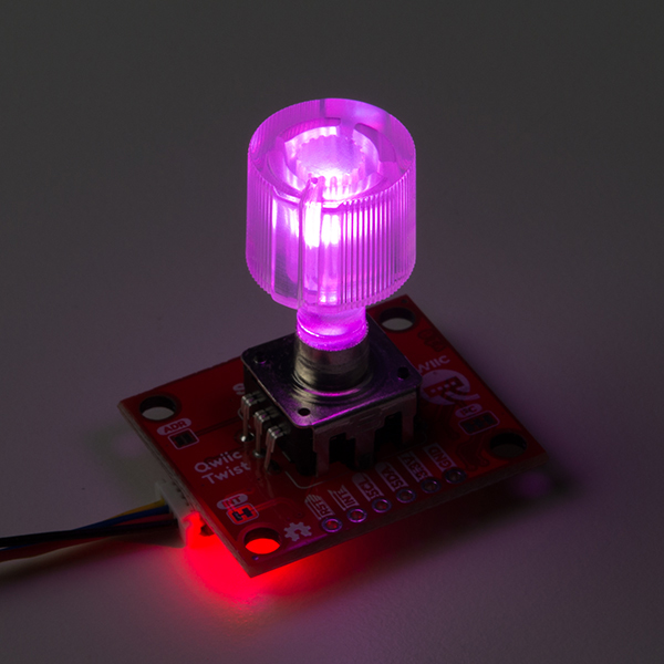
One rotation in the clockwise direction for the rotary encoder increases the overall count by 24 and -24 in the counter-clockwise direction. The number of 'ticks' or steps you have turned the knob are all transmitted over I2C. The red, green, and blue LEDs are all set via software commands and can be digitally mixed to achieve over 16 million colors!
We designed Qwiic Twist with an indent encoder which gives the user a great 'clicky' feel. Additionally, the encoder has a built in button so the user can select an GUI menu or element by pressing down on the it. The Qwiic Twist uses a 6mm shaft and works great with our Clear Plastic Knob listed in the Hookup Accessories below or any other 6mm knob.
We've also written an Arduino library for the Qwiic Twist showing off all the different features of the Twist and for easy interfacing to the breakout including a litany of examples!
Note: The I2C address of the Rotary Encoder is 0x3F and is jumper selectable to 0x3E (software-configurable to any address). A multiplexer/Mux is required to communicate to multiple Rotary Encoder sensors on a single bus. If you need to use more than one Rotary Encoder sensor consider using the Qwiic Mux Breakout.
The SparkFun Qwiic Connect System is an ecosystem of I2C sensors, actuators, shields and cables that make prototyping faster and less prone to error. All Qwiic-enabled boards use a common 1mm pitch, 4-pin JST connector. This reduces the amount of required PCB space, and polarized connections mean you can’t hook it up wrong.
Need a custom board? This component can be found in SparkFun's À La Carte board builder. You can have a custom design fabricated with this component - and your choice of hundreds of other sensors, actuators and wireless devices - delivered to you in just a few weeks.

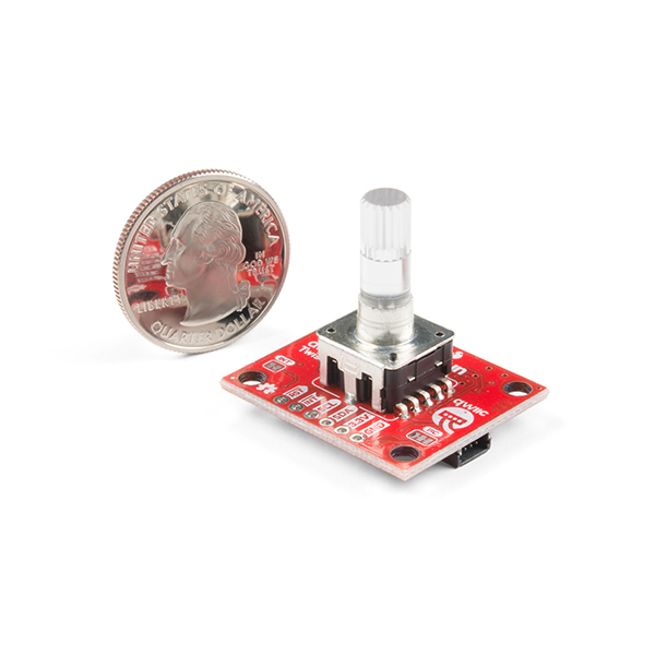
- Length/Width: 1" x 1.2" (25.4mm x 30.5mm)
- Height: 0.984" (25mm)
- Voltage: 3.3V
- Current:
- Approximately 2.8mA LEDs off
- Approximately 40.6mA with LEDs on 100%
- 24 ticks per 360° rotation
- Clockwise and counterclockwise direction is detected
- Software configurable I2C address - up to 111 devices on a single bus
- Built-in momentary button
- RGB LED controlled via PWM allowing for up to 16M colors
- Up to 400kHz I2C communication
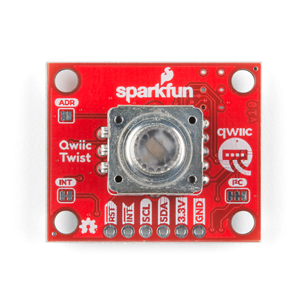
- Jumpers for address selection, interrupt pull up disable, and I2C pull up disable
- I2C Address: 0x3F (Jumper Open, Default), 0x3E (Jumper Closed)
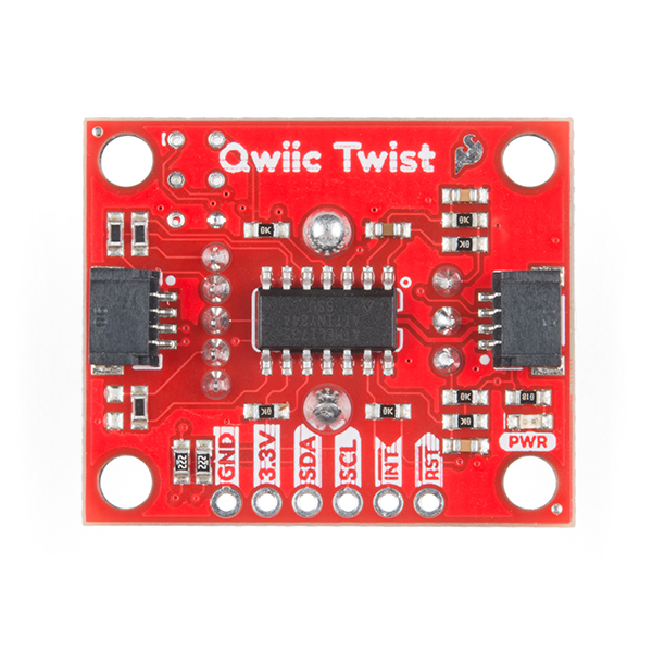
- 2x Qwiic Connectors
- Schematic
- Dimensional drawing: PDF / JPG
- PEL12T Encoder Datasheet
- Eagle Files
- Hookup Guide
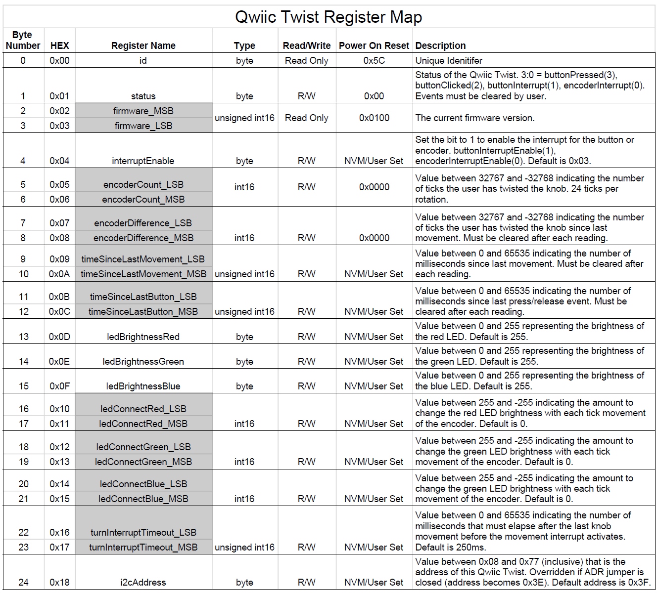
- Register Map: PDF / JPG
- Qwiic Page
- Arduino Library
- Python Package
- GitHub
SparkFun Qwiic Twist - RGB Rotary Encoder Breakout Product Help and Resources
Qwiic Twist Hookup Guide
December 13, 2018
Take your volume knob beyond 11 with the Qwiic Twist digital RGB LED encoder via I2C!
SparkFun Arduino UNO R4 WiFi Qwiic Kit Hookup Guide
July 11, 2023
The SparkFun Arduino UNO R4 WiFi Qwiic Kit is a great way to get started with Arduino and the Qwiic-connect system - use this guide to get started!
Core Skill: Programming
If a board needs code or communicates somehow, you're going to need to know how to program or interface with it. The programming skill is all about communication and code.
Skill Level: Rookie - You will need a better fundamental understand of what code is, and how it works. You will be using beginner-level software and development tools like Arduino. You will be dealing directly with code, but numerous examples and libraries are available. Sensors or shields will communicate with serial or TTL.
See all skill levels
Core Skill: Electrical Prototyping
If it requires power, you need to know how much, what all the pins do, and how to hook it up. You may need to reference datasheets, schematics, and know the ins and outs of electronics.
Skill Level: Competent - You will be required to reference a datasheet or schematic to know how to use a component. Your knowledge of a datasheet will only require basic features like power requirements, pinouts, or communications type. Also, you may need a power supply that?s greater than 12V or more than 1A worth of current.
See all skill levels
Comments
Looking for answers to technical questions?
We welcome your comments and suggestions below. However, if you are looking for solutions to technical questions please see our Technical Assistance page.
Customer Reviews
4.1 out of 5
Based on 7 ratings:
Easy to use
I had this up and running in my project doing everything I needed to do in only a couple hours. One issue I had was that the interrupt-based button press and knob turn functionality didn't update as quickly as needed, so I had to change over to a polling method. I've also noticed that very rarely, the knob seems to miss a tick when turning.
Works great!
I've wanted to experiment with one of these as a user interface, so I got one and I really like it. I had no problems adding the library to my code. Probably one of the easiest things to implement. The center button needs to be debounced, but otherwise, it works beautifully.
Works as advertised
I've played with this for a bit not, and it works as advertised. The QWIIC system makes it easy to connect and you don't need code to constantly monitor rotary motion or debounce the button --> coding is easy. Have not built into a project yet, so no experience with longer-term durability.
Only issue I see is the price, but I'm willing to trade off $ for ease of use - out the thing in your enclosure, hook up the QWIIC cable, and you're set.
Old firmware bugs still unresolved
Amazon had an entire batch of Qwiic Distance boards marked as Qwiic Twists, so after getting 10 wrong items in a row I ordered direct from SparkFun. Finally have some in hand and the first thing you'll find is even now the firmware is bad.
I can confirm this bug is real and in all devices, they even have documented it in their code and have done NOTHING about it in apparently years.
The below is from the demo code they provided:
def get_count(self):
    """Returns the number of indents the user has twisted the knob.

    Notes:
        Looks like there's a bug in the firmware when turning the encoder
        counter-clockwise from the zero position.  It retuns a value that
        is 1 too high.
    """
    return self.read_word(self.TWIST_COUNT)
It Works, but...
The i2c joystick is very light duty and would fall apart quickly in my application. I thought I could take a joystick that was solid as a rock and get it to mate with i2c by soldering the analog joystick pins of a heavy duty joystick to the analog pins of the twist. I am not sure my idea will work and destroying two twists does not seem prudent. I found another direction to get joystick commands to my pi.
Nice package easy to connect and run example codes. Cool colors too.
Had a question though, I am looking to use this run a DC motor forward and backward and none of the examples provide a clue as to how to do that??? I am using a Redboard and a SEEED Motor driver shield V2.0. Got the Redboard to drive the motor alternating back and forth with their example code. I was able to run all of the examples for the Twist. So I know all of the hardware works. However, the code for mapping the encoder steps to how fast the motor runs escapes me. I think I need to use the limit example for maximum but not sure how to link the encoder steps to motor speed. Thanks in advance for any help I can get.
Works fine. I'm a java programmer and found the cpp code easy to translate to something that works with pi4j.
See code example got working below original post...
Original post: Sorry first posted this in the review section so adding it here. I am looking to use this run a DC motor forward and backward and none of the examples provide a clue as to how to do that??? I am using a Redboard and a SEEED Motor driver shield V2.0. Got the Redboard to drive the motor alternating back and forth with their example code. I was able to run all of the examples for the Twist. So I know all of the hardware works. However, the code for mapping the encoder steps to how fast the motor runs escapes me.
So after some experimentation got the following code to work very well. Using it as a DC throttle for model railroad application. Need to reset each time to get it to start up.
//SN300_DC_Throttle
//Sparkfun RedBoard and Encoder
//SEEED Motor Board V2.0
//Reverse switch is DPDT
//Code Modified by David Bradt
/* Read and interact with the SparkFun Qwiic Twist digital RGB encoder By: Nathan Seidle SparkFun Electronics Date: December 3rd, 2018 License: MIT. See license file for more information but you can basically do whatever you want with this code.
This example prints the number of steps the encoder has been twisted.
Feel like supporting open source hardware? Buy a board from SparkFun! https://www.sparkfun.com/products/15083
Hardware Connections: Plug a Qwiic cable into the Qwiic Twist and a BlackBoard If you don't have a platform with a Qwiic connection use the SparkFun Qwiic Breadboard Jumper (https://www.sparkfun.com/products/14425) Open the serial monitor at 115200 baud to see the output */
include "MotorDriver.h"
include "SparkFun_Qwiic_Twist_Arduino_Library.h"
//Click here to get the library: http://librarymanager/All#SparkFun_Twist
const float Factor = 6;
const int buttonPin = 4;
int buttonState = 0.5;
MotorDriver motor;
TWIST twist;
//Create instance of this object
void setup()
{
Serial.begin(9600);
pinMode(buttonPin, INPUT_PULLUP);
Serial.println("Qwiic Twist Example");
motor.begin();
if (twist.begin() == false)
{
// initialize
}
}
void loop()
{
Serial.print("Count: ");
Serial.print(twist.getCount());
if (buttonState == HIGH)
{
// set motor0 to speed based on count
delay(50);
Serial.println();
}
}
I got 6 of these today, was in a hurry on a button box project but it's the 1st time I'm seeing an encoder without ability to use bolts to fix it on enclosure. The only way to fix this one on enclosure is to create 4 holes on the enclosure with spacer and nuts to attach the board. Not painless and looks terrific. So I'm not satisfied, for me it's just useless, this point should be mentioned on product description.
For those writing custom drivers, this device is one of the few you'll encounter that employs clock stretching, so your I2C driver code must be able to deal with that. Funny, so few devices use clock stretching that I had removed it from my I2C code.
The connectColor() function is incorrectly implemented in the standard Arduino library (code is dated November 25th, 2018). The 16-bit colors are supposed to be written Little-Endian, but that function writes them as Big-Endian.
I have ported the Sparkfun library to the Parallax Propeller P2, with the fix for connect_color(), and one or two additional methods for convenience.
Is it possible to know the absolute position?
Please have a look at the documentation including the register map. Both absolute and relative positions are available.
While the firmware maintains absolute position while it is running, the actual encoder used is not an absolute encoder so the firmware can't detect what happens when power is off. It zeros the position at each powerup
wow
nice
Question about the max cps this can handle, I want to use an encoder to track the rotation speed of a motor (to keep two motors on separate drive and slightly unbalanced loads speed matched) and have some different re-purposed motors with 56/250/600 CPR encoders built in. While I could mount up a lower CPR encoder to the system output after all the pulley reduction and filter out any accidental velocity dither from the low cps that's more work and space. Nothing is going terribly fast, ~50RPM at the output max, but that's still in the 150kHz cps range using the lowest CPR motor encoders and I think it may be a bit fast for a board designed for fingers.
Interesting question and I don't have the answer, but let me dig in a bit...
There's a limitation to the mechanical speed of the encoder. Could you turn the encoder on Qwiic Twist at 100RPM? Yep. 1,000 RPM? Probably. But at a some speed the internal bits will fail. Maybe 6,0000 RPM? Hard to say. I've never noticed a max rotation spec on a mechanical encoder but would make for a fun science fair experiment.
As for the software side of things, the Qwiic Twist firmware tracks the encoder changes using hardware interrupts meaning it can track a very high rate of transitions. Off the cuff, the ATtiny is running at 8MHz internal osc, that's 125ns per instruction. The ISR simply increments a counter taking a few instructions so we could probably keep track of over 100,000 'clicks' per second. So as long as your motor is spinning less than 6,000,000RPM the software should keep up.
Interesting, may have to play with the clock as double that cps would be perfect for me. Ideally I'd hook up my own encoder that is a much higher CPR and can handle the RPM (optical disk and is rated for at least 5k RPM) as its already bolted to the motors I have, much simpler build for me than interfacing this 24 CPR encoder into the output drive.
If you do run across a hard cps limit spec, I'd love to know. (another popular encoder project out there is limited to 150 cps according to their site) ;)
Regarding the limits of this integrated encoder, I'd say any use with a motor is inadvisable. Generaly these are based on a contact pad wipe (like a turnpot) and will mechanically wear pretty fast at motor speeds and/or rotation counts.
Can you lovely people make a Sparkfun, ahem, I mean, a Particle library for this Qwiic Twist? I own 2, and my Photon and Electron are lonely. Peace out, old dude.
According to the information on Particle's website... it might already be available (I think). I would use the same search terms a you would for the Arduino IDE, SparkFun Twist, as listed in the hookup guide.
Is there any chance I could get a number of these with a threaded bushing like that on your https://www.sparkfun.com/products/15141 encoder? I love the Qwiic idea, and this product is great, but I'm having a heck of a time coming up with a way to mount it to a front panel.
They would probably be a pain to rework, but it looks like you could swap the parts (it might be a close fit). Otherwise, it might be easier to just use a few standoff screws instead.
There is a CircuitPython library now available for the Qwiic Twist RGB Rotary Encoder and the Raspberry Pi. The source code, examples, installation information and documentation are available on GitHub.
https://github.com/fourstix/Sparkfun_CircuitPython_QwiicTwist
Hey! I was just wondering if the library you guys made for this is blocking or non-blocking code? I'm working with XBees so I want to avoid blocking code in order to read the Xbee as quick as possible.
On another note, did you guys end up making the non-LED version of this? I haven't found it on the store but maybe you did.
Thanks!
Hi there, it sounds like you are looking for technical assistance. Please use the link in the banner above, to get started with posting a topic in our forums. Our technical support team will do their best to assist you.
That being said, the source code for the Arduino library is linked in the hookup guide and on the product page (under the Documents tab... it is easy to miss with the white-on-white color scheme of the tabs). Also, I believe the LEDs are controllable in software if you don't want to use them; it should be mentioned in the hookup guide as well. Otherwise, we haven't created a version without the LEDs.
The library is non-blocking. The library can either poll the device in software or it can use interrupts. You can then check the timeSinceLastMovement register to see when the last movement occurred.
Super! Thanks!
What are the physical dimensions, especially the mounting hole centers? Am I just missing it, or...?
Not your fault - I forgot to add them. Size: 1"x1.2"x0.984". I added a JPG and PDF of the dimensional drawing to the documents page. I also linked to the rotary encoder datasheet so you can glean how tall the various bits of the encoder are. Please let me know if there's a dimension I missed.
I'm not that happy with this product. Even though it works to some extent it misses counts and has switch bounce issues I haven't been able to resolve yet. I have 4 of them chained together and being run using a Teensy 3.5. Even the most basic example provided has issues with it constantly non-stop firing off interrupts. Seems like this is due to I2C communication which when you perform a "GET" command in your loop it will non-stop perform an interrupt. This seems to be creating problems reading the encoder accurately and the push switch also. Is interrupts really needed for Ic2 communications? You can see this by my forum post here https://forum.sparkfun.com/viewtopic.php?f=14&t=49095 The ATTINY84 is suppose to, on idle go into a sleep mode but it looks like it never does. There is a very similar product offered on tindie. It uses a PIC microcontroller instead of an ATTINY84 and looking at the firmware code does not perform an interrupt on every I2C command that gets requested data. Here is that device to compare to https://www.tindie.com/products/Saimon/i2c-encoder-v2/ it is very similar. Actually this one was developed several years ago. I might try these out and see how well they work. Or at least prototype the circuit for testing.
Thanks for reporting the issue! To answer one of your questions: No, you shouldn't need interrupts at all. I prefer to poll each Twist I've got on the bus when I need input from the user. We're working to recreate your interrupt issue as well.
Well, after fiddling around with my code I seem to have it working pretty good now. Thank you.
I'm very happy this product finally exists. I ended up having to make my own version of this for a current project that uses 19 RGB encoders. I also went with the attiny84, but I discovered that there's quite a bit of variance in color (full white) from one to another. I'm using 1% resistors. Have you all at sparkfun found this to be true? I assumed it was because I'm not using constant current.
Thanks! We too use 1% resistors. It will depend on a few things, mainly where you get the encoder from. If the luminosity or forward voltage drop of the LEDs varies significantly you will see variance. For obvious cost reasons we went with a simple current limiter approach and haven't noticed much variability between production units. That said, 'white' is never really white because of the perceived brightness of green vs red vs blue.
This seems like a really cool device. But I am wondering, are there any plans to offer this exact same thing but without the LED?
I can envision quite a few applications where this would be really handy. But the price is a bit high if you don't need/want the LED.
Thanks, Joe
Good idea. We designed the hardware to support a normal, non-RGB encoder (with built in switch). I'll see if I can get a product put together for it.
Btw - does anyone have a preference for encoders with indents (the clicky feel as you twist) versus encoders without? The non-illuminated encoder market is quite large so we have lots of options.
I prefer the indents. I like the tactile feedback, they give. The clicky feeling is just so re-assuring.
That is a tough question for me to answer. It seems that just about every application in which I have seen encoders like this use indents. But I suppose there might be applications in which these would not be preferable. Maybe you can find two encoders that have the exact same footprint and mechanical specs but one has indents and the other doesn't? That would mean you could design one board (or perhaps use the board you already have) and just change the BOM.