- Home
- Product Categories
- RTC
- SparkFun Real Time Clock Module - RV-8803 (Qwiic)


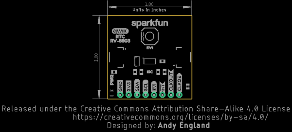
SparkFun Real Time Clock Module - RV-8803 (Qwiic)
The SparkFun RV-8803 Real Time Clock Module is a Qwiic-enabled breakout board for the RV-8803 RTC. The RV-8803 boasts some impressive features including a temperature compensated crystal providing extremely precise time-keeping, low power consumption, and time stamp event input along with a user-programmable timing offset value. The RV-8803 also has an improved I2C interface compared to the RV-1805 RTC that removes the need to sequence commands/writes to the device. Best of all, the temperature compensation comes factory calibrated. Utilizing our handy Qwiic system so no soldering is required to connect it to the rest of your system. However, we still have broken out 0.1"-spaced pins in case you prefer to use a breadboard.
Adding a real-time clock to your project is the perfect way to get more accurate data; timing or otherwise. Using the Qwiic connector makes for a fast, solid way to incorporate this into your project. The RTC module has counters for hundredths of seconds, seconds, minutes, hours, date, month, year and weekday with a number of alarm and interrupt settings available as well. Plus the large operating temperature range (-40 to +105°C) and temperature compensated crystal makes for a good addition for field applications or harsh environments.
The SparkFun Qwiic Connect System is an ecosystem of I2C sensors, actuators, shields and cables that make prototyping faster and less prone to error. All Qwiic-enabled boards use a common 1mm pitch, 4-pin JST connector. This reduces the amount of required PCB space, and polarized connections mean you can’t hook it up wrong.
- 1x SparkFun Real Time Clock Module - RV-8803
- 1x 12mm CR1225 Coin Cell Battery
- Factory Calibrated Temperature Compensation
- High Time Accuracy
- ±1.5 ppm 0 to +50°C
- ±3.0 ppm -40 to +85°C
- ±7.0 ppm +85 to +105°C
- 1.5V to 5.5V Operating Voltage Range
- 240nA @ 3.3v Low-Power Consumption
- I2C Address: 0x32
- Periodic Countdown Timer Interrupt function
- Periodic Time Update Interrupt function (seconds, minutes)
- Alarm Interrupts for weekday or date, hour and minute settings
- External Event Input with Interrupt and Time Stamp function
- Programmable Clock Output pin for peripheral devices.
- Operating temperature range: -40 to +105°C
- 2x Qwiic Connectors
SparkFun Real Time Clock Module - RV-8803 (Qwiic) Product Help and Resources
The ClockClock Project
October 8, 2020
Tell the time with this fantastic Alchitry project using clocks to make a clock!
Real Time Clock Module - RV-8803 (Qwiic) Hookup Guide
April 2, 2020
A Hookup Guide for the SparkFun Real Time Clock Module - RV-8803 (Qwiic). Learn how to integrate the RV-8803 into your next time-keeping project.
Core Skill: Programming
If a board needs code or communicates somehow, you're going to need to know how to program or interface with it. The programming skill is all about communication and code.
Skill Level: Competent - The toolchain for programming is a bit more complex and will examples may not be explicitly provided for you. You will be required to have a fundamental knowledge of programming and be required to provide your own code. You may need to modify existing libraries or code to work with your specific hardware. Sensor and hardware interfaces will be SPI or I2C.
See all skill levels
Core Skill: Electrical Prototyping
If it requires power, you need to know how much, what all the pins do, and how to hook it up. You may need to reference datasheets, schematics, and know the ins and outs of electronics.
Skill Level: Rookie - You may be required to know a bit more about the component, such as orientation, or how to hook it up, in addition to power requirements. You will need to understand polarized components.
See all skill levels
Comments
Looking for answers to technical questions?
We welcome your comments and suggestions below. However, if you are looking for solutions to technical questions please see our Technical Assistance page.
Customer Reviews
5 out of 5
Based on 2 ratings:
It works as advertised
Works fine, bothe hardware and software.
RV-8803 RTC
This is a great and very accurate RTC
This should have the PSW pin exposed like the RV-1805!
Hi. I understand that RV-8803 has an I2C address 0x32 while the 9DoF Razor IMU M0 has 0x68 and 0x0C. It mean that I can connect their I2C lines so that can the Razor can read the time from the RTC while also reading the measurements from the IMU, right? What should I consider if I plan to implement this? Thank you.
Hi there, it sounds like you are looking for technical assistance. Please use the link in the banner above, to get started with posting a topic in our forums. Our technical support team will do their best to assist you.
Psst! You guys forgot the mounting holes!
In all seriousness though, I understand that you're trying to fit as much functionality into a 1" square as you can and that sacrifices must be made, but I was really left scratching my head. The RV-8803 deviates from the standard Qwiic design by not having at least two mounting holes, so standoffs can't be used. On the backside, it can't be soldered to a protoboard with 0.1" headers because of the CR1225 battery holder. On the topside, the Qwiic connectors also prevent using 0.1" headers. Are the only options right-angle 0.1" headers and 8-pin female headers? Please correct me if I'm wrong!
Mounting aside, I'm super excited to see a low-power temperature-compensated RTC hit the streets! I've been waiting for a DS3231SN replacement for over 3 years!
4 years later and still wishing this thing had mounting holes!
Does the battery backup right to VDD? So we can assume the backup time is battery(mAh)/RTCpower?
It is not, if we check out the schematic you can see that it is basically diode Or'ed with 3.3V into VDD on the RTC.
Ok, that's what I thought. So when there is no power to the RTC, the battery takes over. Is there no conflict when power is applied and does the diode-OR prevent any battery leakage? I assume given the math (46mAh/260nA) that the battery has a natural drain that's faster than the RTC itself so in the end, the backup life is essentially the battery lifespan.
It's this sweet low leakage diode which leaks only 100 nA at 50V.
The graph's look to be about 2 nA leakage at 3V
Is the I2C address 0x32 or 0x64? The hookup guide references both addresses, but also says the address can't be changed.
the 7-bit unshifted address is 0x32, however, the LSB determines whether a read or write occurs. Adding this LSB gives you 0x64 for a write and 0x65 for a read, but the base 7-bit address is still 0x32.
Thanks for the clarification!
@chipmc: The broken out 0.1" shaved headers can get you to the pin for alarm/interrupt. If the Qwic connector would have included this, it would not have the universal appeal of being Lego like. Your point reminds me of the upcoming Arduino Portenta connector, (aka Eslov self-identification port), but its extra pin is the wrong direction for your use case. Too bad they didn't choose the SM06B-SRSS-TB(LF)(SN) instead. I love how JST has pre-crimped wires that fit any in the SH family, alleviating the need for the pricey crimper tool.
Hi, can we have a compare/contrast with the DS3231 chip based clock. This looks very good worth the switch?
Perfect example of why I hate Qwic. I get that this system makes it easy to get started but, it has a serious drawback - there are only four wires. One of the main reasons for having a real time clock is for alarms which are typically expressed as interrupts which enable the microprocessor to sleep or do other things while the clock counts time. But you can't do this with Qwic because they - for some reason - chose to make it only four wires! BTW, this is true for all manner of devices such as accelerometers, magnetometers, thermometers. It would have added next to nothing to make Qwic a 5 or 6 wire connector. Why reduce the functionality and utility of these sensors?
The issue with having a 5th line be Interrupt or reset or something to that effect is that not all interrupts are the same, some are active high while most are active low. If there were a fifth line on Qwiic that were Interrupt, some sensors may try and pull it high, some may pull it low, leading to all sorts of issues. That's just the start, say we do have a fifth line and it's connected to interrupt, you receive an interrupt - but have no idea where it came from. Some sensors also have an interrupt input instead of an output, so one sensor firing an interrupt could trigger the interrupt input on another sensor when we wanted to trigger something on the microcontroller.
The solution to this problem is to have a dedicated GPIO to service the interrupt for each individual sensor so you know which sensor on the bus to ask for data when you receive an interrupt. If you had all of the interrupts bussed together, as you suggest, this option would not be possible as an interrupt from any one sensor would trigger an interrupt routine on all of the GPIO's connected to sensors (not good)
With a daisy-chainable system, sacrifices must be made.
OK, so buy the RTC, set it to 1982 and go back and tell Philips that you want an out-of-band interrupt line. Might as well complain about USB too, while you're back there.
Four pins works for a large majority of devices but compromises have to be to keep things simple. That's why everything is broken out to pins on the edge of the board where you can put your own connector and implement whatever > 4 wire standard you'd like.