- Home
- Product Categories
- Addressable
- Fairy Lights - Addressable RGB (5m)


Fairy Lights - Addressable RGB (5m)
Affectionately dubbed "Fairy Lights" for their similar appearance, these addressable RGB LED string lights are a great way to light up any project with no soldering required. The insulated strings come in 5m lengths with one RGB LED every 5cm for a total of 100 LEDs. These LEDs have an IP65 waterproof rating to protect your LEDs.
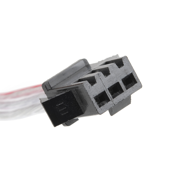
The string of lights terminate on either side with a locking 3-pin JST connector, one male and one female. The wiring and pinout is listed below.
- Red Stripe = 5V
- "White" (Middle) = DAT
- "White" (The Other Side) = GND (wire appears to be connected closest to the LED's dotted polarity marker side)
- Color: RGB
- LED Quantity: 100
- Operating Voltage: 5 VDC
- Control IC: WS2812
- Light Spacing: 50mm
- String Length: 5m
- Wire Color: Silver
- IP Rating: IP65
Fairy Lights - Addressable RGB (5m) Product Help and Resources
Addressable LED Strip Hookup Guide
November 23, 2016
Add blinking lights to any holiday decoration with our Holiday Lights Kit using WS2812-based addressable LEDs!
WS2812 Breakout Hookup Guide
July 24, 2013
How to create a pixel string with the WS2812 and WS2812B addressable LEDs!
WS2812-Based Protocol
Our catalog has the red/green/yellow wire JSM-SM pair [ CAB-14575 ] to mate with the connectors on the Fairy Lights. The bag that holds it has information about the wiring and pinout.
- Red Stripe = 5V
- "White" (Middle) = DAT
- "White" (The Other Side) = GND (wire appears to be connected closest to the LED's dotted polarity marker side)
The "male" housing receptacle with (female pin sockets) like the one shown below is the DIN side. The datasheet indicated that the LEDs communicated with "SPI". We tested the LEDs and it uses the WS2812-based protocol. You could use the Neopixel or FastLED library to control the LEDs.
Core Skill: Programming
If a board needs code or communicates somehow, you're going to need to know how to program or interface with it. The programming skill is all about communication and code.
Skill Level: Rookie - You will need a better fundamental understand of what code is, and how it works. You will be using beginner-level software and development tools like Arduino. You will be dealing directly with code, but numerous examples and libraries are available. Sensors or shields will communicate with serial or TTL.
See all skill levels
Core Skill: Electrical Prototyping
If it requires power, you need to know how much, what all the pins do, and how to hook it up. You may need to reference datasheets, schematics, and know the ins and outs of electronics.
Skill Level: Rookie - You may be required to know a bit more about the component, such as orientation, or how to hook it up, in addition to power requirements. You will need to understand polarized components.
See all skill levels
Comments
Looking for answers to technical questions?
We welcome your comments and suggestions below. However, if you are looking for solutions to technical questions please see our Technical Assistance page.
Customer Reviews
3.8 out of 5
Based on 5 ratings:
1 of 1 found this helpful:
Purchased four of these, have not gotten any to work
Purchased 2 units a months or so ago. As mentioned in other reviews, the connectors are reversed from every other light strip I own. This caused me to reverse polarity the power. I then cut off the connectors and resoldered, but I guess the damage was done. After buying 2 more last week, I carefully made new connections but still do not have any active lights. These seem like a good idea and appear suited to a project I would like to build, but currently I have spent over $85 plus tax for no result
Finally got them working
My light strands seemed to be bad. I was using the female side (male pins) that connects to another strip of pins as the input. Was expecting that it didn't matter which side I used to test them. The male side (female pins) needs to be used for the connection to the MCU. The +5v pin is marked in BLUE with my strands on the male connector end. The female connector end is marked in red. I am able to put 2 strands together and they both work. The yellow tag that labels the wires is correct. In my opinion it is labeled on the wrong end as that is the end that connects to another strand, instead of the input end. Using the FastLED library with WS812 GRB configuration. Good luck!
Exactly What I Needed
These lights were exactly what I needed! I had been looking for small yet bright lights for a costume piece and these worked perfectly. I weaved them into a vest and though the rest of the electronics still require additional modifications, these lights did their job splendidly.
Amazing!
Made a "firefly jar" for my deck. All comments regarding which end to use are correct. The sticker comes on the wrong side... Otherwise, an ESP8266 and a level shifter and my fireflies are dancing to the command of my phone!!
Very good and useful
I am working on an art project that will use fairie light strings. I bought one of the Sparkfun strings and am delighted. The markings for polarity were completely wrong, but I figured it out. The literature talks about the red stripe. The tag was on the end with a blue stripe, with the other end having an unlabeled red stripe.. I used the end with the label, and got pin polarity using the blue stripe. I used the Sparkfun Arduino libraries and example programs to begin development. The library and code were a great basis to evolve my work. I quickly developed a small fascinator using the one string I bought. I have designed the installation to use 18 strings, but now Sparkfun is out of stock. I could not find a phone number to discuss when they might be getting more light strings in. Frustrating.
The 09-Mar-2021 batch is wired opposite. Socket (male housing) is input.... Blue = 5V, Middle = DAT, End = GND.
This is also true of the 26-APR-2021 batch
My batch, 22-Apr-2021 is also backwards with socket being input end. Some info on power consumption: with all LEDs off, my string draws 41.8 mA for all 100 "pixels." I assume this is the draw of the controller chip in each pixel. It appears that each LED full on draws about 4.25 mA. So a pixel in "white mode" with RGB all full on is about 12.75 mA. At 5 volts that is about 0.064 W which is close to what the spec sheet says, 0.07 W. This was a pretty quick test but at least it gives you some idea of the order of magnitude. Also the order of the colors seems to be RGB for when you set up the protocol.
The wiring on the new batch seems off. Only 2 of 3 chains worked. The female end has a blue strip (no red one) and they seem to be in backwards in the connector. I had to put jumper wires in to daisy chain with the new ones with my old strand...
do you have a part number for the connector?
Unfortunately, that information isn't readily available from the manufacturer.
I could possibly this LED connector; however, with the COVID restrictions in place, I can't easily verify that for you.
I have not seen a clear, sheathed JST-SM connector before. However, our catalog has the red/green/yellow wire JSM-SM pair [ CAB-14575 ] as "Santa Claus Impersonator" explained. I was able to get a hold of the LEDs and the bag that holds it has information about the wiring.
The "male" housing receptacle with (female pin sockets) like the one shown below is the DIN side. I tested it using the FastLED library and these seem to be using the WS2812-like protocol.
will that thin wire really hold with 6 amperes (100 leds * 60mA each when full white) flowing through it?
The datasheet from the manufacturer seems to be lacking on that information. However, I don't think that the LEDs will be capable of drawing the amount of current you are estimating (60mA). As you mentioned, the wire looks fairly thin and will most likely act like a "current limiting resistor".
This seems a little short of documentation. How do you control them? The "data sheet" (more of a brochure really) says SPI, but with only one non-power pin, it can't actually be SPI …
Hi,
Yeah, we were wondering about that as well with the datasheet. The datasheet provided by the supplier did not make sense. We tested the LEDs and it uses the WS2812-like protocol. You could use the Neopixel or FastLED library.
What addressable LED type are these compatible with?
Hi!
The datasheet provided by the supplier did not make sense. We tested the LEDs and it uses the WS2812-like protocol. You could use the Neopixel or FastLED library.