- Home
- Product Categories
- Arduino Boards
- SparkFun MicroMod ATP Carrier Board

SparkFun MicroMod ATP Carrier Board
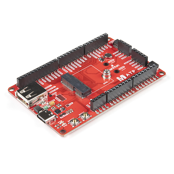
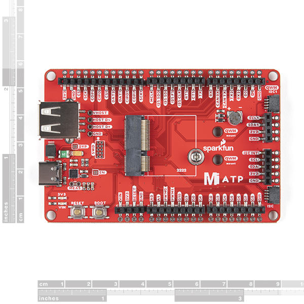
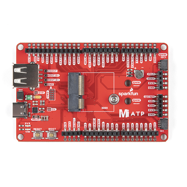
Access all the pins (i.e. ATP) of the MicroMod Processor Boards with the SparkFun MicroMod ATP Carrier Board! This board breaks out the MicroMod Processor Board's pins on the M.2 connector to 0.1" spaced female headers and PTH pads on the edge of the board. This Carrier Board is great if you're interested in testing out different MicroMod Processor Boards for your application.
A modern USB-C connector makes programming easy. In addition to the pins broken out, two separate Qwiic-enabled I2C ports allow you to easily daisy chain Qwiic-enabled devices. We've exposed the SWD pins for more advanced users who prefer to use the power and speed of professional tools. A USB-A connector is provided for Processor Boards that have USB Host support. A backup battery is provided for processor boards with RTC. If you need a "lot" of GPIO with a simple-to-program, ready for market module, the ATP is the fix you need. We've even added a convenient jumper to measure the current consumption for low power testing.
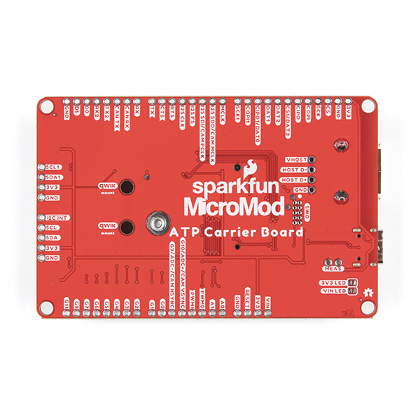
MicroMod is a modular interface ecosystem that connects a microcontroller “processor board” to various “carrier board” peripherals. Utilizing the M.2 standard, the MicroMod standard is designed to easily swap out processors on the fly. Pair a specialized carrier board for the project you need with your choice of compatible processor!
- M.2 Connector
- Operating Voltage Range
- ~3.3V to 6.0V (via VIN to AP7361C 3.3V Voltage Regulator)
- 3.3V (via 3V3)
- Ports [1]
- 1x USB type C
- 1x USB type A Host
- 2x Qwiic Enabled I2C
- 1x CAN
- 1x I2S
- 2x SPI
- 2x UARTs
- 2x Dedicated Analog Pins
- 2x Dedicated PWM Pins
- 2x Dedicated Digital Pins
- 12x General Purpose Input Output Pins
- 1x SWD 2x5 header
- 1mAh battery backup for RTC
- Buttons
- Reset
- Boot
- LEDs
- Power
- 3.3V
- Phillips #0 M2.5x3mm screw included
[1] Note: Depending on the design of the Processor Board, not all the pins may be accessible.
MicroMod ATP Carrier Documentation:
MicroMod Documentation:
SparkFun MicroMod ATP Carrier Board Product Help and Resources
MicroMod All The Pins (ATP) Carrier Board
October 21, 2020
Access All The Pins (ATP) of the MicroMod Processor Board with the Carrier Board!
MicroMod STM32 Processor Hookup Guide
May 13, 2021
Get started with the MicroMod Ecosystem and the STM32 Processor Board!
Qwiic Digital Desk Sign with MicroMod
June 30, 2022
Make a Qwiic-enabled digital desk sign with a MicroMod SAMD51 Processor Board's USB Host and a USB keyboard!
Designing with MicroMod
October 21, 2020
This tutorial will walk you through the specs of the MicroMod processor and carrier board as well as the basics of incorporating the MicroMod form factor into your own PCB designs!
Getting Started with MicroMod
October 21, 2020
Dive into the world of MicroMod - a compact interface to connect a microcontroller to various peripherals via the M.2 Connector!
MicroMod Alorium Sno M2 Processor Board Hookup Guide
April 22, 2022
Get started with the MicroMod Alorium Sno M2 Processor Board!
MicroMod SAMD51 Processor Board Hookup Guide
October 21, 2020
This tutorial covers the basic functionality of the MicroMod SAMD51 and highlights the features of the ARM Cortex-M4F development board.
Core Skill: DIY
Whether it's for assembling a kit, hacking an enclosure, or creating your own parts; the DIY skill is all about knowing how to use tools and the techniques associated with them.
Skill Level: Noob - Basic assembly is required. You may need to provide your own basic tools like a screwdriver, hammer or scissors. Power tools or custom parts are not required. Instructions will be included and easy to follow. Sewing may be required, but only with included patterns.
See all skill levels
Core Skill: Programming
If a board needs code or communicates somehow, you're going to need to know how to program or interface with it. The programming skill is all about communication and code.
Skill Level: Rookie - You will need a better fundamental understand of what code is, and how it works. You will be using beginner-level software and development tools like Arduino. You will be dealing directly with code, but numerous examples and libraries are available. Sensors or shields will communicate with serial or TTL.
See all skill levels
Core Skill: Electrical Prototyping
If it requires power, you need to know how much, what all the pins do, and how to hook it up. You may need to reference datasheets, schematics, and know the ins and outs of electronics.
Skill Level: Competent - You will be required to reference a datasheet or schematic to know how to use a component. Your knowledge of a datasheet will only require basic features like power requirements, pinouts, or communications type. Also, you may need a power supply that?s greater than 12V or more than 1A worth of current.
See all skill levels
Comments
Looking for answers to technical questions?
We welcome your comments and suggestions below. However, if you are looking for solutions to technical questions please see our Technical Assistance page.
Customer Reviews
5 out of 5
Based on 1 ratings:
Coolest Breakout Board
This thing is the best breakout board to do embedded testing during design and general Arduino shenanigans. USB C is more useful than you think and with 1A of 3v3 you don't need an external power supply.
If you are wanting to try out what MicroMod has to offer, this is THE board to get.
Make an arduino compatible version! Or is this already arduino compatible?
Yes, it's Arduino compatible. Check out the example section 'Blink': https://learn.sparkfun.com/tutorials/micromod-all-the-pins-atp-carrier-board#example
But is the hardware form factor Arduino? Could I put an Arduino Mega shield on the ATP for example?
If you compare the pinout, the MicroMod ATP Carrier Board does not use the Arduino Mega 2560 hardware footprint.
Is there a BOM for this board? I would like to know the part# for the USBC (J1) connector.
Please make an ATP MicroMod Function board, ideally with prototyping holes as well.
To ask a similar question as, are there any Eagle library parts out there that represent this board. You can usually find standard boards like DUE or the Teensy 4.1 and Eagle library components so you can build of of them but I am not sure about this APT board because I am not sure of this follows a standard open source footprint.
Need clarification on the schematic for +3.3v Pins and Gnd pins. The schematic labels them as 2 * 2 & 1 * 7 respectively. That makes no sense as to what all the pins are.
I'm not sure why Eagle is naming the 3.3V and GND pins this way, but I think it has to do with the fact that there are multiple pins on the M.2 connector for both.
For VCC, M.2 pins 2 and 74 are both VCC. For ground, it's M.2 pins 1,7,33,36,39,45 and 75.
Keep in mind there's a gap in the connector where there are missing pins, those missing pins are still numbered so the small section of the connector covers pins 1-33 and then the larger section starts at pin 32 and goes up to pin 75.
Check the data sheet for the M.2 connector for an idea how the pins are numbered on the connector. You can also look at this image to see the power and ground pins.
I just want to add a little transparency into this unique Eagle feature. When creating a symbol in Eagle, it's possible to combine multiple pins (e.g. 1-10) under one net (e.g. 3.3V and GND). In this case there are multiple 3.3V and Ground pins that share the same net. So in the pins you mentioned "2 * 2", the left number is the lowest pin number grouped together in the 3.3V net , and the right number is the total number of pins in the group. Likewise "1 * 7", "1" is the lowest numbered ground pin and "7" is the total amount of pins in the grouping.
Are there any plans to produce a protoboard that plugs into the headers on this board? I'm thinking something similar to the Arduino footprint prototyping board that Sparkfun makes. I've had great success using that protoboard to make permanent circuits and interfaces, as well as experiment with projects.