- Home
- Product Categories
- Biometrics
- MyoWare 2.0 Muscle Sensor

MyoWare 2.0 Muscle Sensor
Using our muscles to control things is the way that most of us are accustomed to doing it. We push buttons, pull levers, move joysticks... but what if we could take the buttons, levers and joysticks out of the equation and control it with our muscles? The MyoWare® 2.0 Muscle Sensor is an Arduino-compatible, all-in-one electromyography (EMG) sensor from Advancer Technologies that allows you to do just that! The MyoWare 2.0 Muscle Sensor has been redesigned from the ground up with a new easy-to-use, compact design and upgraded with the latest and greatest chipset improving sensor performance and reliability. The innovative snap connector system eliminates the need to solder connections for the MyoWare 2.0 ecosystem. It's that easy: stick on a few electrodes (not included), read the output voltage and flex some muscles!
The MyoWare 2.0 Muscle Sensor measures muscle activity through the electric potential of the muscle, commonly referred to as surface electromyography (EMG or sEMG for short). When your brain tells your muscle to flex, it sends an electrical signal to your muscle to start recruiting motor units (the bundles of muscle fibers that generate the force behind your muscles).
The harder you flex, the more motor units are recruited to generate great muscle force. The greater the number of motor units, the more the electrical activity of your muscle increases. MyoWare 2.0 Muscle Sensor will analyze the filtered and rectified electrical activity of a muscle and output a signal (0-VIN volts, where VIN signifies the voltage of the power source) that represents how hard the muscle is being flexed.
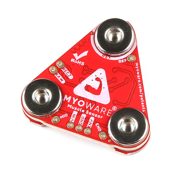
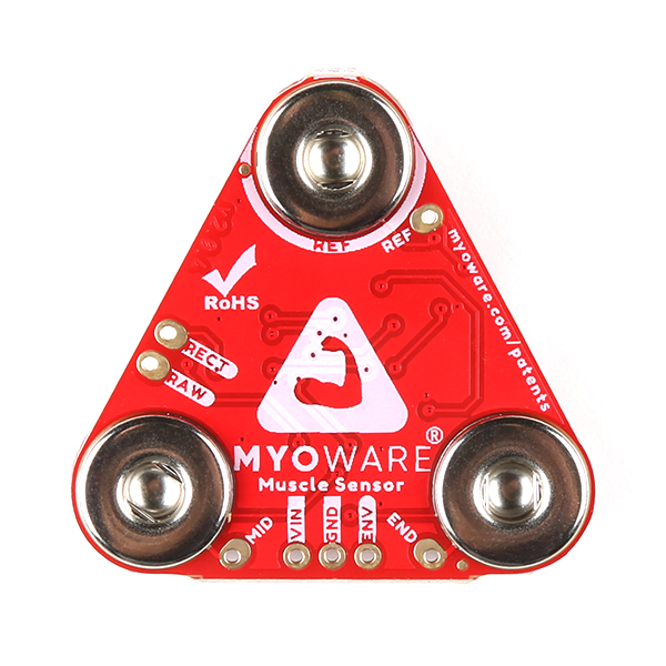
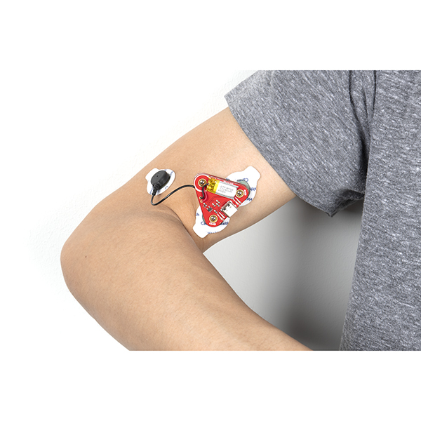
The MyoWare 2.0 Muscle Sensor builds upon its previous wearable design that allows you to attach biomedical sensor pads directly to the board itself, getting rid of those pesky cables. This board includes a single-supply voltage of +3.3V to +5V, three output modes, reverse polarity protected power pins, and indicator LEDs. Additionally, we have developed a few shields (such as the Cable, Power, and LED shields to name a few) that can attach to the MyoWare 2.0 Muscle Sensor to help increase its versatility and functionality! The muscle sensor’s snap connector system makes it easier to stack shields together. The top side connectors link to power and the sensor’s EMG envelope output while the bottom side links to the input electrodes.
Measuring muscle activity by detecting its electric potential has traditionally been used for medical research. However, with the advent of ever shrinking yet more powerful microcontrollers and integrated circuits, EMG circuits and sensors have found their way into all kinds of control systems such as video games, robotics, and prosthetics! Biomedical sensor pads can be found in the Recommended Products section below to be purchased separately.
Note: MyoWare and the Muscle Sensor are not intended for use in the diagnosis of disease or other conditions, or in the cure, mitigation treatment, or prevention of disease, in a man or other animals.
The MyoWare® 2.0 ecosystem consists of shields that easily interface with the MyoWare® 2.0 Muscle Sensor, which is a low-cost, Arduino-compatible, all-in-one electromyography (EMG) sensor from Advancer Technologies. The innovative connector system allows users to easily snap shields together with a compact low profile and connect to a microcontroller's analog input to measure raw, filtered, and rectified electrical activity of a target muscle. This eliminates the need to solder connections between boards.
This product is a collaboration with Brian Kaminski from Advancer Technologies. A portion of each sales goes back to them for product support and continued development.
- Wearable Design
- Supply Voltage
- Minimum: +2.27V
- Typically: +3.3V to +5V
- Maximum: +5.47V
- Input Bias Current
- 250pA, max 1nA
- Reverse Polarity Protection
- Three Output Modes
- Raw EMG
- Rectified
- Envelope
- Expandable via Shields
- MyoWare® 2.0 Muscle Sensor Form Factor
- 3x Female Snap Pins (Input Electrodes)
- 3x Male Snap Pins (Power and EMG Envelope Output)
- LED Indicators
- VIN
- ENV
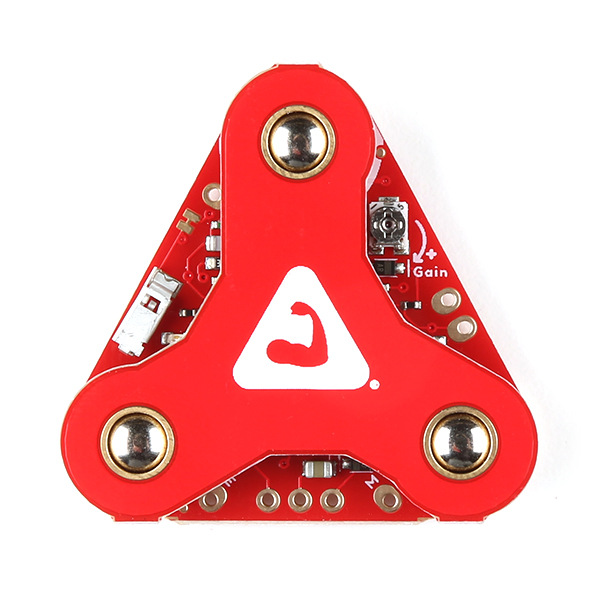
- Reference Electrode Jumper
- Specially Designed For Microcontrollers
- Adjustable Gain
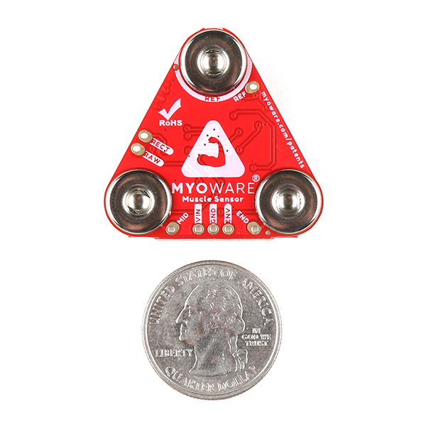
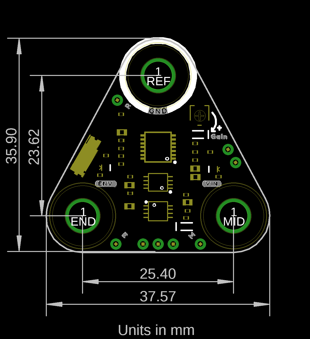
- Board Dimensions
- 37.57mm x 35.90mm (1.48” x 1.41”)
Revision Changes: The following changes for V2.0.4 include:
- PCB board thickness increased.
- NPTH for snap connector buttons.
- Updated footprint for snap connectors buttons with slots for improved cleaning.
- Updated size of reference pin's jumper pad.
- Board Dimensions
- Hookup Guide
- Advancer Technologies: MyoWare® 2.0
- Quickstart Guide (4.37MB)
- Advanced Guide (9.00MB)
- Patents [1]
- Arduino Reference Language: ArduinoBLE Library
- GitHub Example Repo
- MyoWare 2.0 Ecosystem Page
[1] Note: This product is patent protected. To prevent counterfeit boards, the Eagle design files and GitHub hardware repository are not shared for boards in the MyoWare 2.0 ecosystem.
MyoWare 2.0 Muscle Sensor Product Help and Resources
Getting Started with the MyoWare® 2.0 Muscle Sensor Ecosystem
April 1, 2022
The MyoWare® 2.0 Muscle Sensor, an Arduino-compatible, all-in-one electromyography (EMG) sensor from Advancer Technologies. In this tutorial, we will go over the features and related shields to connect the sensor to a muscle group.
Core Skill: Programming
If a board needs code or communicates somehow, you're going to need to know how to program or interface with it. The programming skill is all about communication and code.
Skill Level: Rookie - You will need a better fundamental understand of what code is, and how it works. You will be using beginner-level software and development tools like Arduino. You will be dealing directly with code, but numerous examples and libraries are available. Sensors or shields will communicate with serial or TTL.
See all skill levels
Core Skill: Electrical Prototyping
If it requires power, you need to know how much, what all the pins do, and how to hook it up. You may need to reference datasheets, schematics, and know the ins and outs of electronics.
Skill Level: Rookie - You may be required to know a bit more about the component, such as orientation, or how to hook it up, in addition to power requirements. You will need to understand polarized components.
See all skill levels
Comments
Looking for answers to technical questions?
We welcome your comments and suggestions below. However, if you are looking for solutions to technical questions please see our Technical Assistance page.
Customer Reviews
3.7 out of 5
Based on 3 ratings:
This thing is amazing.
I love this thing! Better product than i had imagined it'd be!
Myoware 2.0 product support and shipping cost
I have found the product support from Sparkfun to be very inadequate. The only support is via a Reddit forum where you post a question and pray that their support staff reads and answers it adequately. I believe that the customers for the products fall in a broad spectrum of knowledge about the products and require different levels of support and the Reddit forum model is inadequate. I think the product sales could easily go up with better support. At this time a customer CANNOT talk to any human at Sparkfun, nor can you email for any support! The shipping cost is super expensive. For even a few items costing about $20, the lowest shipping cost is about $12 with delivery in 5 business days; this is not in sync with shipping costs by other vendors today.
SparkFun has a forum that you can post in as well https://forum.sparkfun.com/viewforum.php?f=143
Really sad to see sparkfun moving to selling things, that instead of having a schematic, it has a pointer to a patent where 10 seconds go googling would clearly show even the first claim is invalid BS.
Hi, I wanted to confirm. The Instrumentation amplifier and the bandpass filters are included in the module. Is that right? Or do we need to create this circuitry by ourselves? Thanks
Where is the schematic for this? What is this actually doing? Is it just an OP-amp?
Hi!
I just noticed your comment. Sorry, the product is patent protected. To prevent counterfeit boards, the Eagle design files and GitHub hardware repository are not shared for boards in the MyoWare 2.0 ecosystem.
However, there is some information in the block diagrams. If you have not checked it out, be sure to look in the Getting Started with the MyoWare® 2.0 Muscle Sensor Ecosystem: MyoWare 2.0 Muscle Sensor and MyoWare Advanced Guide. There are a few stages to amplify, filter, rectify, and process the envelope.