- Home
- Product Categories
- LED Drivers
- MIKROE 4x4 RGB Click


MIKROE 4x4 RGB Click
4x4 RGB Click is a matrix of 16 "intelligent" RGB elements, forming a 4x4 display screen. These LED elements feature internal logic, which allows them to communicate directly with the MCU. These intelligent LEDs are meant to be cascaded: the elements communicate by a single line with the host MCU and they feature a signal reshaping section, so the data gets to the adjacent element with no losses or distortion.
Thanks to the high brightness of the LED elements and their color consistency, this Click board™ can be used in various decorative applications, simple pattern displays, color number displays, and due to a cascade nature of the Click board™ itself, they can even be used for building larger screens and displays.
4x4 RGB Click carries sixteen LED elements labeled as WS2812 - intelligent LED elements with an integrated control, from Worldsemi Corporation, arranged in 4 by 4 matrix. These LED elements are composed of red, green, and blue LED segments, forming an RGB LED cell, with their intensities controlled by the integrated logic section. This integrated control section allows separate 8 bit control of each RGB segment, forming 24bit color palette, allowing 16,777,216 different colors to be displayed.
The integrated logic communicates with the host MCU by a single line. The data transfer protocol uses the non-return-to-zero (NRZ) communication mode, so the timing of the data signal is critical. The logical 1 consists of a signal with a certain HIGH and LOW timing. The logical 0 also consists of a signal with a certain HIGH and LOW timing. The difference between logical 0 and 1 is in the timings of HIGH and LOW signal states, as illustrated in the picture below:
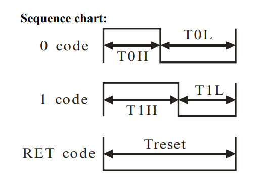
The values of these timings are shown in the following table:
- HIGH level timing for logic 0 | T0H | 0.5us | ±150ns
- LOW level timing for logic 0 | T0L | 0.8us | ±150ns
- HIGH level timing for logic 1 | T1H | 0.7us | ±150ns
- LOW level timing for logic 1 | T1L | 0.6us | ±150ns
- LOW level timing for RESET | TRST | > 50us
This means that sending logical 1 to the WS2812 device, the host MCU has to keep the data line HIGH for 0.7us then LOW for another 0.6us. Once the first 24bits are completed this way, the RST impulse will latch the data in.
The communication line can be selected with the onboard SW1 switch. It offers selection between the mikroBUS™ RST and CS lines, labeled as IN1 and IN2. The communication voltage level can be set by the onboard SMD jumper, labeled as the IO LEVEL and it can be chosen between 3.3V and 5V, allowing interfacing to both 3.3V and 5V MCUs.
The power supply for the LED elements is provided by the MCP1826, a low-voltage, low quiescent current LDO regulator from Microchip, which can provide current up to 1A. While the logic voltage can be selected between 3.3V and 5V rails, the LED power supply is derrived from the 5V mikroBUS™ power rail. It is reduced to 3.5V by the LDO, and distributed to the LED supply inputs of the WS2812 elements.
The PWM pin of the mikroBUS™, which is labeled as OUT on this Click board™, allows cascading of multiple 4x4 RGB Click devices. It simply routes the data line back to the mikroBUS™, allowing it to be re-used for the next 4x4 RGB Click, and so on. The length of the whole chain is limited only by the communication speed, required to scan through all the LED devices, in order to maintain a reasonable refresh speed.
- Interface: GPIO
- Compatibility: mikroBUS™
- Dimensions: 57.15 x 25.4mm
- Input Voltage: 3.3V or 5V
MIKROE 4x4 RGB Click Product Help and Resources
Comments
Looking for answers to technical questions?
We welcome your comments and suggestions below. However, if you are looking for solutions to technical questions please see our Technical Assistance page.
Customer Reviews
No reviews yet.