- Home
- Product Categories
- Memory Cards
- SparkFun microSD Transflash Breakout

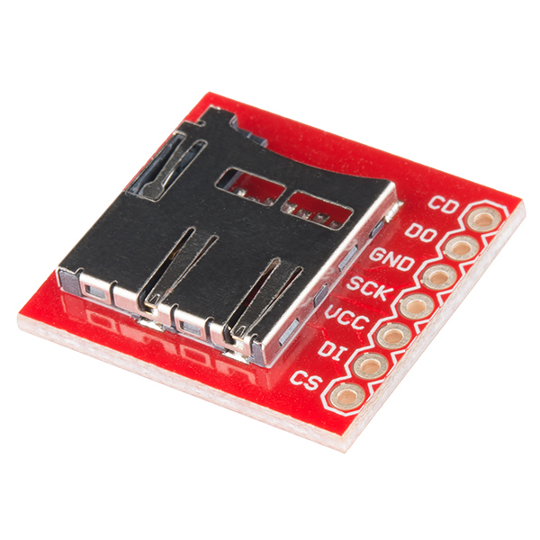
SparkFun microSD Transflash Breakout
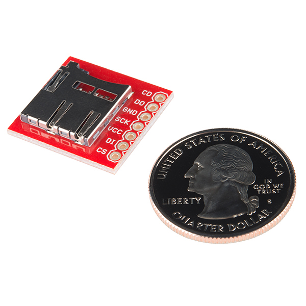
Breakout board for the microSD socket that is not much bigger than your fingernail. Compatible with the SPI interface found on any SD card, this tiny form factor was created for cell phone storage and is perfect for your next MP3 project! Board comes fully assembled and tested.
The bare socket is available.
Need a custom board? This component can be found in SparkFun's À La Carte board builder. You can have a custom design fabricated with this component - and your choice of hundreds of other sensors, actuators and wireless devices - delivered to you in just a few weeks.

- Schematic
- Eagle Files
- Datasheet
- Adding SD to a Router - Thanks Jake! Eagle Layout as well!
- mbed Example
- GitHub
SparkFun microSD Transflash Breakout Product Help and Resources
Example Tutorials
We also have a tutorial using the microSD Shield that might be of some use => https://learn.sparkfun.com/tutorials/microsd-shield-and-sd-breakout-hookup-guide#sd-card-breakout-boards . Try looking at the design of the microSD shield to connect to an Arduino Uno footprint. There are other widgets on our storefront that use the microSD (like the OpenLog or LilyPad MP3 to name a few). Try looking at the Eagle board layouts and schematics for an idea of how to connect a microcontroller to the SD and microSD cards.
Here's additional tutorials that might be of some use:
Logic Levels
You must bring the voltage down from a 5V Arduino with a logic level converter. If you don't have a logic level converter, you can use some resistors like this the ones that were used in our old logic level converter [ https://learn.sparkfun.com/tutorials/using-the-logic-level-converter#hardware-overview ].
Note: In relation to the microSD card's pinouts [ http://elasticsheep.com/2010/01/reading-an-sd-card-with-an-atmega168/ ] and the pins of this breakout:
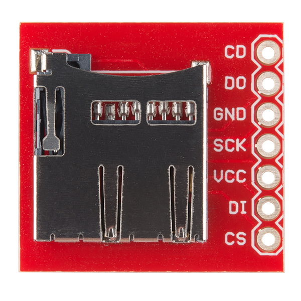
microSD Card Pinout = breakout board silkscreen = microcontroller
DAT0 = D0 = MISO
VSS = GND = GND
CLK = SCK = SCK
VDD = Vcc = 3.3V
CMD = DI = MOSI
CD/DAT3 = CS = CS/S
We also sell a separate board called the "SparkFun Level Shifting microSD Breakout" https://www.sparkfun.com/products/13743 that has the level shifting built in.
Arduino Library
To use with Arduino, there is an SD card library that has already been written => http://arduino.cc/en/Reference/SD.
Core Skill: Soldering
This skill defines how difficult the soldering is on a particular product. It might be a couple simple solder joints, or require special reflow tools.
Skill Level: Noob - Some basic soldering is required, but it is limited to a just a few pins, basic through-hole soldering, and couple (if any) polarized components. A basic soldering iron is all you should need.
See all skill levels
Comments
Looking for answers to technical questions?
We welcome your comments and suggestions below. However, if you are looking for solutions to technical questions please see our Technical Assistance page.
Customer Reviews
3.7 out of 5
Based on 15 ratings:
6 of 6 found this helpful:
Well... It works.
It works well for what it is.
As people have said in the comment section, the card when inserted DOES NOT extend all the way to the edge, so don't expect to embed this in an enclosure. This might depend on the exact card you're using but I have two different cards here and neither of them reach the edge.
It would have been nice to see all SD card pins broken out, but for my purposes I only intend to use SPI mode and this board is great for that.
1 of 1 found this helpful:
Does what it says
Just a simple breakout for a microhd socket with all the signals you need to talk to the card over spi.
Very handy
If you have tried soldering wires onto a microSD card socket, well, forget it. Not impossible, but very, very difficult.
What this does is make it simple to attach a .1" header to the little board so it can be connected to a breadboard easily. It can also plug into a 6 or 7 pin female header - the CD pin in rarely used.
The microSD socket used for this is from conn4u.com and is very economical; as long as you want 3000 of them. If you were hoping on using the Gerber files for this for your own PC board, you will find them to be pretty useless because of the source of the socket. MicroSD sockets are not all that popular to have public PC board layouts for and they are complex and have pretty close tolerances. I understand why the conn4u.com part is used: it is pretty good and it is cheap if you are going to use a lot of them. I wish the manufacturers (Hirose, Amphenol, etc.) made available either nicer drawings or layout files for these things.
Pull-ups
Having the option to install pull-ups on the PCB would be very helpful.
I'll pass your comment along for future consideration if we revise this product. Thanks!
Needed to add uSD card to a Teensy 3.1
Had an application where I needed to add a uSD card to a Teensy 3.1. This allowed me to verify my PCB design. I was also able to start coding while I waited on OshPark to finish my boards.
So far 1 out of 2 working
I bought 3 of these breakout boards and fought with one for 2 days figuring that there had to be something wrong with my code. As it turned out the breakout board was faulty and as soon as I switched out the board everything worked great. I haven't tried my third one yet.
I'm sorry to hear that you received a faulty board. If you'll contact our tech support team, we'll be happy to arrange a replacement or refund for you.
does the job
does the job. works great.
would be nice if you added a 1uF or .1uF cap across VCC and GND. The spec for hooking up uSDs says to do this. Would be nice if you had a SMT cap on the next rev of the board.
just a thought.
Perfect for 3.3V projects
I got tired of stripping regulators and LEDs off of imported TransFlash boards to use them for low-power projects. I bought the SparkFun TF board because it is just the socket, so it works perfectly at 3.3v. I have two for my breadboards - one with a right angle connector and one with a straight connector.
Exactly what I needed.
Haven't used it yet. Hope to use it with an AVR or Propeller micro for an MP3 player eventually.
I would prefer this over the level-shifting breakout for some applications, but ...
This is good for lower power and lower cost, compared to the the level-shifting breakout, but ...
The connections should be located behind the socket, which would make the breakout board it easier to handle and would facilitate mounting in an enclosure. The board may be slightly larger, but that is not important.
And to consolidate other person's recommendations:
Add a decoupling capacitor Vcc to gnd, 0.1 uf to 1 uf. Provide pull-up resistor pads (or just add resistors with cut-able trace) Breakout all sd connections.
Latch broke quickly, otherwise good
The latch broke in a couple days of use. I ended up just removing the spring and now I just pull out the card and it works fine.
Cannot be used in SD mode
Unfortunately this board did not work for us because only 6 of the 8 pins are brought out from the uSD socket.for wiring. We ended up buying the microSD sniffer board for our application.
Hi, Sorry to hear that this didn't work for your needs. Please contact us if you would like to return it for a refund. We'll be happy to help you out. https://www.sparkfun.com/returns
Arrived non functional, replacement works
The first one I received will not lock a card in place so is non-functional.
Update: I got a notification that a replacement has shipped, thanks.
Update 2: Replacement arrived and is functional.
We have your ticket in our system and will get you taken care of soon!
I like it. It does exactly what I want.
Very simple and easy to integrate.
Where would I find the Eagle .lbr for this component?
It would be nice if the card slot butted up against the end of the board or even extended over the edge, which would allow this device to be mounted in a enclosure. As it is you need to use your thumbnail to insert the card. Also, the CD pin seems to be wired directly to the case and is always shorted to ground.
Check out Nate's comment below: http://www.sparkfun.com/products/544#comment_20549
On the current version of this that I just ordered, the microSD card is about 1 mm away from the edge on the inside when loaded. So if you mounted this in an enclosure, you would need fingernails to push it in. So I think they still need to move the socket over slightly.
Hi,
I'm wondering (for those who have used it) what is the supply current for this device? for example logging analog data from an mcu?
Thanks
Card reader worked great with Sparkfun Pro Micro 3.3V. For those looking to hook it up and get everything running, use any standard SD example in Arduino >=1.02 and wire as follows:
And finally make sure you set: const int chipSelect = 10;
Thank you! I did exactly this and uploaded File>Examples>SD>CardInfo (a sketch by the always amazing Ladyada) and it worked perfectly. Oddly, I forgot to change the chipSelect from 4 and it still worked o_O
I would like to attach to Sparkfun Pro Mini 5V. Would I connect to the same pins as with the micro? I have the 5 V supply so would I just use a resistor to regulate the voltage to the sd card?
It's not quite that simple. The SD card requires power and I/O at 3.3V; you can either add a substantial amount of extra circuitry to a 5V Arduino to do this, or you can just use a 3.3V Arduino Pro (regular or mini). We recommend using a 3.3V Arduino Pro with this board.
Sorry to dig up an old thread, but I bought one of these for use with a 5V Mega 2560, and it wasn't until after delivery that I realized it can only work at the 3.3V level. So I bought the BOB-12009 bi-directional logic level shifter, but now I realized I have no idea how to hook it up to this board, since I'm not sure what voltages the various pins on the Mega are running at. Is the SCK pin on the Mega 5V? What pins do the standard SD library use on the Mega, and what voltages are they at, so I know which ones I need to run through the level shifter? Thanks.
My pro micro 3.3v doesn't have a port D14, D15, or D16. What am I not understanding?
It should. On the silk screen they are pins 10, 16, 14 and 15.
In the schematic for the Pro Micro 3.3V, if you look at the header (JP6), they're labeled D10, MOSI, MISO, SCK - while if you look at the microcontroller in the schematic you'll see them additionally labeled again with D10, D16, D14 and D15. So just ignore the 'D' in DaveMcC's comment :)
oops, I have a pro mini, not a pro micro...sorry!
if anyone is curious, this is how you connect this to a pro micro 3.3v: SD - Arduino CS - D10 DI - D11 VCC - VCC SCK - D13 GND - GND DO - D12
Then, just use standard SD libraries.
Note that for this microSD socket the CD switch are reversed (for DC = OPEN for card inserted, CD = GND for card not inserted)
Does this board work with the SDuFAT library for the Arduino?
Yes, I used it so I could prototype on a 5v Arduino, but I had to set the clock speed to SPI_QUARTER_SPEED.
Just bought this board and neither of my two microSD cards reach all the way to the edge, so I'm not sure what dimensions they're using to measure their schematics... Regardless, they should move the slot closer to the edge so that this board can be embedded and used with a wider variety of cards.
Also, the SD Specification linked in the description is outdated and doesn't cover SDHC cards so you'll have to look elsewhere for that info.
The Arduino SD library said "Card type: SDHC" but "Could not find FAT16/FAT32 partition." The problem was, as someone found in the SparkFun forums, that the card communication couldn't keep up. In the CardInfo example sketch I switched SPI_HALF_SPEED to SPI_QUARTER_SPEED and that fixed it. Hope this helps someone else having the same problem!
My setup was Arduino Uno => jumpers to breadboard => Logic Level Converter => jumpers to elsewhere on breadboard => SD card breakout; it sounds like once the connection is more direct the problem may go away.
The SdFat library docs actually call this out:
Can i connect these to a arduino fio?
has anyone noticed how the microSD library for eagle isn't the package they're using here? or the microSD at all? the one that matches this one and the non-breakout board is the transflash card from adafruit... so everyone who wants to build their circuit with this and/or the non-breakout one has the wrong design file.
Comment bellow by DZJP is PERFECT if you have and Arduino UNO.
I have used this breakout board successfully with an Arduino UNO, the RedBoard, Arduino Pro Mini 3.3V and 5V, for the Arduino UNO, RedBoard and proMini 5V, I recommend using a LogicLevel Converter found here at Sparkfun. The connections are:
Once you have this connections, you can open up in Arduino File>>Examples>>SD, you need to switch CS--> pin 4 to CS-->pin 10 in the code, the comments highlight this. The CS goes to the SS pin ( Slave Select) you can specify other Digital pin for this (You could use the Digital Pin 4 for this if you like), though I only tried it with Digital Pin 10 that is why I reported this connection.
For me it is more elegant than a shield.
Thanks for this! "> C0 --> Digital Pin 12"
There isn't any C0? What's left for me is VCC, D0 and CD.
Hello, thanks I have corrected that there was no C0. Hope this helps =)
Any specific reason why you used the pin 10 for the CS instead of the pin 4 like in the Exemples?
No specific reason, just because the connections were easier for me. You could use CS->DigitalPin4 and keep it like that in the code, that pin varies from shield to shield, in the Sparkfun's SD Shield it is Digital pin 8. In the case of the Breakout board you have the choice to choose this pin. The CS goes to the SS (Slave Select Pin), this specifies to which device the SPI bus is going to talk, in case you have several SPI devices.
Thx so much. That helped me incredibly well, everything works perfect! :)
Awesome! Thank you :)
I know others have said this, but a hex buffer or MOSFET level shifting on board would make interfacing with 5V systems a breeze. Thanks, y'all haven't let us down yet.
after asking a question regarding the USB breakout board literally a few minutes ago i feel kinda stupid for asking this question but can this board hook up directly to the Arduino to start storing memory? I don't like the large size of the shield and feel boards of this size have a certain je ne sais quoi.
basically i would like to know if this board works as is or if it would need some sort of hex converter chip or something?
A hand solderable microSD surface mount card socket is Yamaichi PJS008-2003-0. Its eight signal pins, two card detect pins and four mounting solder tabs all extend away from the socket to be accessible. None are underneath the socket. It is a push-push type with normally open card detect switch when no card is inserted and its signal pins are located opposite from the card insertion side. The card inserts upside down when viewing the socket from the top, so it probably is meant to be mounted on the bottom of a pcb. Available from Mouser as part 945-PJS008-2003-0.
How do I connect this to an arduino?
Take a look at the MicroSD Shield which does most of the work for you. (There are links to the libraries you’ll need on that page as well.)
If you do want to connect this board to an Arduino you can, but be sure you know what you’re doing (take a look at the SD Shield schematic). In particular SD cards run on 3.3V; connecting them to a 5V Arduino will damage them.
How much is the hole spacing?
How i connect Breakout Board for microSD Transflash with arduino uno and which library will used
Take a look at the MicroSD Shield which does most of the work for you. (There are links to the libraries you'll need on that page as well.)
If you do want to connect this board to an Arduino you can, but be sure you know what you're doing (take a look at the SD Shield schematic). In particular SD cards run on 3.3V; connecting them to a 5V Arduino will damage them.
Can i use this with ATMEGA16?
Hey anyone know if this works for SDHC cards?
Yes - and also SDXC. Keep in mind that this is just a breakout board - i.e. it wires the contact pins from the SD socket out to a nice breadboard-friendly 0.1" pitch set of pads that you can solder a header to.
SD, SDHC and SDXC all share the same physical pins and pin assignments - they just work differently internally (allowing greater storage space, faster interface speeds, etc.)
It would be great to see a version of this breakout board that came complete with the 50k pull-up resistors required for SPI mode. I also wish these breakout boards would all come standard with mounting holes. Some have them and some don't - but they are essential for mounting these things in any sort of semi-permanent device! Especially something like this that is bound to get pushed and prodded when a card is inserted or removed!
We try to find a balance between small size and the ability to add mounting holes for all of our boards. Generally for small boards without mounting holes, we recommend trying to use something like velcro or hot glue for attachments.
Is this part compatible with 16 and 32 GB cards?
The pinout is the same, but the initialization is slightly different. It's a protocol issue, and there's code floating around that'll do the trick. The Beaglebone works in that regard.
I will be installing this in my remote control and keylogging my parents security lock on the tv! Now I can watch TV after school MWAHAHA
Can you estimate when you will have more of these in stock?
Anyone test this on a Beaglebone or Beagleboard connected to the MMC pins? I want to see if it works with MicroSDHC.
EDIT: Crud! Just checked the pinouts, and this only has 7 pins when I need all 8! This will be SPI only. Looks like I need to get the socket and find a way to bake on the component so I can prototype a shield.
What power am I supposed to run this off of. I got it working on 5v, but according the the micro SD shield's spec it says that it regulates the voltage to 3.3 to protect the SD card, so should I just use the 3.3v on the arduno to power this?
You should use 3.3V for power and I/O, so connecting it to a 3.3V Arduino (Pro or Pro Mini) would be ideal. If you want to use it in a 5V system, take a look at the shield schematic for the level-translation circuit we use.
Does anyone know how fast you can write data to the SD card (speed in msec) using this product. Can't find any specs. I read somewhere for another microSD type datalogger that they could achieve about 44 msec through serial port.
what do these Mean;
CD
D0
SCK
VCC
DI
CS
These pin names are in generic or SPI terminology rather than SD card terminology.
What does CD2 indicate (pin 7)? Is it connected to a physical switch inside the connector? My understanding was that CS is pulled high when a card is inserted, and you could use that to detect a card.
I like this board a lot but there are some serious flaws.
I understand that the socket was recessed from the edge so an "inserted" card is flush. I don't see how this is actually useful to start with. I'd rather not be forced to use my nail. A concession however would be to move the pins back so you can just cut/sand down the PCB to be flush without taking out the CD pin.
The uSD holder has a huge issue as well. The two tabs that deflect when a card is inserted and disconnect the case from the CD line are not very reliable (poor design choice, but cheaper to make) and can even easily be permanently bent so a card is always detected. They are also exposed making that more prone to happening.
Other uSD slots are better because the CD switch is pushed by the edge/side of the card only in the last mm of insertion, well after all contacts have been made.
A couple of the above links are broken....
PIC MMC Interface Project and SD Card Specification.
Suggestion: Can you use official names of connections (e.g. DAT0, CMD, ...) if there is a new release of the board ?
Is microSD electrically the same as the full size SD card? I.E. Can i use this part as a direct replacement for a standard size SD card?
How fast is the IO using a hand soldered ribbon cable? Personally getting real slow, unreliable IO on the order of 30000bits/sec using hand soldered SD cards.
In my opinion, this board should be redesigned. I think a lot of people would buy this for permanent installation in their projects to avoid having to hand-solder a bare micro-sd connector. For this purpose, it would be better if the connector were flush with the edge of the board and it the solder pads were spread around more to increase stability when soldered to a header.
The board was designed to be embedded and retain easy access to the microSD card. If you have a chance, checkout the Eagle files where we indicate the microSD card in three postions: popped out, being pushed in, and loaded. In the loaded position, the card is right on the edge of the PCB allowing for easy push-to-remove access.
Why is this board the same price as an entire shield? Come on Sparkfun, both your breakout boards for SD Card a massively over priced!
Dah! Good point. This is a very old design. A lot has changed since we first starting carrying the microSD socket many years ago. I'll review the pricing and see what has to come down.
Ah, this brings in so many possibilities.
if anyone still reads this, useable schematic can be found on the micro sd shield page
Sorry about that! I've updated the schematic to a more readable PDF.
Hi! Are the schematics and/or PCB layout for Eagle and/or KiCAD available for this board? Better yet, I am looking for the KiCAD and/or Eagle part library/module. Any help much appreciated! Thanks and have a nice day!
Andrew Lynch
It would help if there was an example with compilable sketch of how to use this with an Arduino (pro mini, mega) that would just read back some card info.
I think I have mine hooked up right, but the DO doesn't seem to drive either high or low. But that might be because the program needs a different wiring (other than the obvious miso mosi sclk ss ground power).