- Home
- Product Categories
- Other LEDs
- SparkFun LED Matrix - Serial Interface - Red/Green/Blue

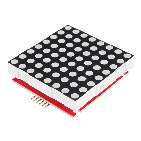
SparkFun LED Matrix - Serial Interface - Red/Green/Blue
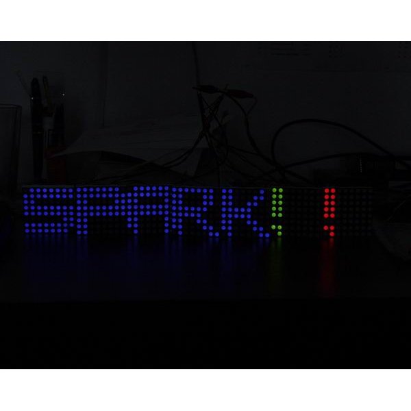
This is a large sized RGB LED Matrix with a backpack that has been designed to take SPI serial input and display any graphics you pass it. All the refreshing and communication control is taken care of by the backpack. It's even reprogrammable! 7 software selectable colors are available!
Unit comes with a Red/Green/Blue LED Matrix assembled with a RGB Matrix Backpack Controller.
Check out the LED Coffee Table tutorial!
Example Projects:
- Example Software for older RGB Serial Matrix
- Wiring Example
- Example deployment by Nokinomo by Mr. Nick Hall
- Ladies and Mens Room Mixup by Vanessa Carpenter
- Ethernet LED Matrix tutorial by Owen Osborn
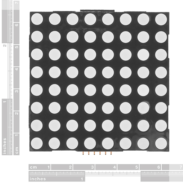
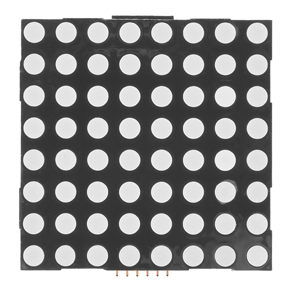
- 2.38x2.38" square
- Max width of backpack including connector pins - 1.1"
- [Schematic](http://cdn.sparkfun.com/datasheets/Components/LED/RGB Matrix.pdf)
- [Eagle Files](http://cdn.sparkfun.com/datasheets/Components/LED/RGB Matrix.zip)
- Matrix Backpack Controller Datasheet
- RGB Serial Matrix Firmware
- Sample Interface Code
- Sample Arduino Sketch
- Triple Color LED Matrix Datasheet
- GitHub
SparkFun LED Matrix - Serial Interface - Red/Green/Blue Product Help and Resources
Core Skill: Programming
If a board needs code or communicates somehow, you're going to need to know how to program or interface with it. The programming skill is all about communication and code.
Skill Level: Competent - The toolchain for programming is a bit more complex and will examples may not be explicitly provided for you. You will be required to have a fundamental knowledge of programming and be required to provide your own code. You may need to modify existing libraries or code to work with your specific hardware. Sensor and hardware interfaces will be SPI or I2C.
See all skill levels
Core Skill: Electrical Prototyping
If it requires power, you need to know how much, what all the pins do, and how to hook it up. You may need to reference datasheets, schematics, and know the ins and outs of electronics.
Skill Level: Rookie - You may be required to know a bit more about the component, such as orientation, or how to hook it up, in addition to power requirements. You will need to understand polarized components.
See all skill levels
Comments
Looking for answers to technical questions?
We welcome your comments and suggestions below. However, if you are looking for solutions to technical questions please see our Technical Assistance page.
Customer Reviews
No reviews yet.
hi -- I had the usual problems getting this thing to talk to a "real computer" so i wrote up my steps and posted all the code I used. More or less, I run a tiny stub piece of code on an Atmel that listens to its UART over 9600bps and sends commands to a connected backpack over SPI. This lets me then control the matrix from almost anything at a pretty good FPS without any complications. Here it all is, enjoy:
https://github.com/bwhitman/rgb-backpack-controller
Hello,
I developed an alternative firmware with new features:
The 255 colors limit was just a software limitation. I managed to squeeze 32768 colors, but the flickering was unacceptable. Perhaps with more code optimization, it can be done.
Please note however that input data format had to be changed. You now need 3 bytes for each 2 pixels (RRRRGGGG BBBBRRRR GGGGBBBB).
Download the firmware and Arduino library here.
Bye.
Tutorial (once you find it) Helps a lot.
5V->VCC, GND->GND, D10->CS,D11->MOSI,D13->SCLK
V5 still isn't installed by default on the backpacks I just received.
V5 firmware.
I'm not sure why this isn't officially on the Matrix product page..
http://www.sparkfun.com/news/452
http://www.sparkfun.com/tutorials/200
I've attached the v5 firmware and arduino library in a message at this link.
http://forum.sparkfun.com/viewtopic.php?f=14&t=26503&p=120394#p120394
Dave
LED Matrix - Column Statistics https://www.youtube.com/watch?v=-DWBC0Wwv7g
Part 2
It seems that the placement of the LEDs on that initial screen is based on how many board the system things are connected together. This arrangement means that the system thinks that two board are connected together. This explained it all. Every OTHER frame was being displayed because the second frame was being sent to a phantom board.
Upon further analysis of the firmware, it seems that after 255 times of the board being power cycled, the EEPROM location that stores that there is 1 board being connected gets rewritten. So i just power cycled my board a few time and it started behaving properly again....
I guess during the development of the firmware, they encountered this situation before. That would be the only reason i would think they had the routing to rewrite to the eeprom. Anyone from sparkfun care to comment.
Part 1
So this was interesting... I noticed that my animations started to look a bit choppy. When I slowed down my animation it looked like it was updating the screen two columns per refresh, as opposed to 1 (which i programed). After some thought i hypothesized that it was only printing ever OTHER frame. I confirmed this behavior with some short test code.
So i started to audit my code to see if i was doing something wrong, or had hold timers to short or anything like that. I didnt find any error in my code.
After getting slightly confused i stood back and just started to observe again. It was then that i noticed something weird. When the board starts up, it displayed 2 red, 2 green, and 2 blue dots. This is done from the firmware on the device. Usualy this is displayed on LEDs 0-5. However, my board was using LEDs 1-6. I thought this was weird and assumed that i corrupted the boards firmware. But i still had to double check what the boards firmware did.
Is it possible to order just the backpack, without the LED matrix?
It would be nice if this came with female headers. That way, the connection would be temporary.
I would like this as well, I think that this would be a nice controller for the rgb button pad, using 4 of them to make a 8x8 array and this backpack as the led controller.
Hi,
For a project i'm working on I want to PWM control the LED's. I wrote new firmware for this using WinAVR.
You can download my firmware from:
http://www.microframework.nl/2008/12/02/rgb-led-matrix-now-with-pwmrgb-led-matrix-now-with-pwm/
LED Matrix - Column Statistics - RFid access Video Youtube
Hi There, Crazy question here- As LEDs can also function as photodiodes (to quote a source, this is accomplished with an arduino by setting up a circuit with a single LED- "anode is connected to a digital pin and the cathode is connected to a an analogue input pin. Don’t forget a current limiting resistor in each LED"). Is it possible to something like that with this matrix?
Has anyone gotten this to work via python on the Raspberry PI? I am using the RPi.GPIO library and am able to write a single frame. The problem is, I cannot seem to clear that is being displayed unless I cut the power to the matrix. Also, when I power this matrix up, the number "1" appears. That is nowhere in the documentation. Is there a more up to date doc for this?
Are there any wiring diagrams for the backpack to arduino? It is not obvious from the wiring diagrams supplied here.
Can someone give me a list of all the possible colors with PWM? thanks.
I have one of those but the shape of the backpack is different from the one that is in those photos, mine has vertical pins with 90 degrees to the board instead of the ones on those photos also it says RGB Led Matrix Controller V2 on the backpack, anyone have a working code for that version ?
The code here do not work for me for Arduino .
Thanks
As long as the HW is the same (which I guess is), have a look at https://github.com/fornellas/SFRGBLEDMatrix. I had a LOT of problems with the original firmware...
If the green and blue LEDs have a typical voltage of 3.3V (3.5V max) and the red LEDs have a typical voltage of 2.0V (2.2V max) and all the current resistors are the same value (which appears to be 100 ohms on the schematic), isn't that going to screw up the brightness of the RED LED? The blue and green are running about 17 mA and the red is 30 mA (right at the peak current limit for the LED).
I need only backpack controller
Another possible improvement could be to load the three shift registers in parallel by utilizing the unused io pins. I might try reworking my board to see if it will work. WRT using the SPI to program the shift register: I could be wrong, but the SPI looks fixed to the pins that are used to load the frame data onto the board.
For the next revision, how about using hardware SPI to control the shift registers? That would allow for higher color depth.
https://github.com/fornellas/SFRGBLEDMatrix
Is 4096 enough? If not, you will have to buy some of this:
http://iteadstudio.com/store/index.php?
main_page=product_info&cPath=50_51&products_id=337
Any chance I could get some of these with square pixels instead of circles?
I had a question about the matrix schematic in the data sheet. It shows the negative lines 26,26,24,23,10,9, and 8 extending past the last LED in the row and looks as if it connects with the positive line 18. Row 7 does not show this and I do believe that the above lines should not extend past the last LED.
Is there a reason for this or is this just a mistake and I should ignore it?
Hi, is it possible to use a higher SPI rate than 125KHz (recommended in the datasheet of the panel). The ATmega328P has a 16MHz oscillator. Can't it run the SPI at around 4MHz as an SPI client?
I tried to drive the panel with Cheetah SPI master. It's ok at the rate of 100KHz, but not at the 200KHz.
Did anyone else tried a higher rate?
MacOS X 10.6.8;
(Arduino 0022);
Arduino Uno;
Sparkfun 8x8 RGB matrix with Backpack;
I try to install the new Firmware following this guide: http://www.sparkfun.com/tutorials/200
However, when I run this command:
avrdude -P /dev/tty.usbmodemfa131 -b 19200 -c avrisp -p m328p -v -U flash:w:RGB_Backpack_v5.hex
Then receive a signature error
avrdude: Device signature = 0x000000
avrdude: Yikes! Invalid device signature.
Double check connections and try again, or use -F to override
this check.
Therfore I turn on the -F flag:
avrdude -P /dev/tty.usbmodemfa131 -b 19200 -c avrisp -p m328p -v -U flash:w:/Users/i822913/Downloads/RGB_Backpack_v5/RGB_Backpack_v5.hex -F
At this point I receive a verification error
avrdude: verifying ...
avrdude: verification error, first mismatch at byte 0x0000
0x0c != 0x00
avrdude: verification error; content mismatch
I thought I could ignore this validation error, but the original issue (off by one pixel) persists.
I have some backpacks with the atmega168 chips and I have some with the atmega328p chips and with the v5 firmware loaded, the atmega168 boards are noticeably dimmer than the 328p's. Is there something that needs to be changed in the firmware to accommodate this? Looking on atmel's site, it doesn't appear that there is any functional difference between the two but frankly I have no idea.
Any help is greatly appreciated.
I have asked many times for the backpack alone to be sold separately... But nothing...
I'm with the others who never got answered and would like to see just the backpack for sale. I already have stacks of led matrix's would be nice/lazy not to have to build the circuits for them.
Just saying....
Hello LEDers,
Help! Pluged in my power supply - LED array produced a happy face then suddenly stopped after the 3rd attempt. Now just displays a few LEDs when powered up. Recommendations?
What is the procedure for resetting the device? Has the firmware gone into a strange mode?
Ok so for a 1920x1080 TV using this we would need an array of 240x135 which would mean buying 32,400.
So a 1920x1080 @ 15Hz with 8-bit colour should cost £1,193,292.00 to build the display part not even the digital decoder stuff. I think Sony and the other guys have done well to make then for £200 with 100Hz :D
Which firmware are these shipping with these days? Is there any way to determine that through software?
I just got four of these. I'm seeing some minor corruption on the display when testing with the RGBMatrix library, which based on comments I've read, would seem to imply that I don't have the latest firmware (V5).
Finally, is there a way to access the ISP without adding a 6-pin header to the backpack? Could I use the MISO, CS, SCLK, GND, VCC from the SPI output header along with the MOSI pin from the SPI input?
I just received some of these the other day. They were definitely not running version 5. If your unit boots up and displays a large number corresponding to the position in the chain, it's version 5. I was able to use an Arduino to re-program my board to v5. Details of the procedure is here: http://www.sparkfun.com/tutorials/200
I didn't solder in a header - I just held an unsoldered header in position for the couple of seconds it took to flash. The flash procedure worked flawlessly. Unfortunately, v5 is just as useless as previos versions. In fact, possibly more so. The problem is that the command character (%) is recognized anywhere in the data, not just the first position, so you have to make sure that there is no '%' in your data stream. Also, v5 introduces a new special character 0x26 which resets the frame to the beginning. Now there's two characters you have to watch out for! Also, the firmware still resets to default after 255 power cycles!
Thanks Erazmus! Based on what you've said, I don't have V5 on mine either.
Are you still observing corruption on the displays even AFTER updating to V5 and taking care not to use either of the control characters?
The RGBMatrix example looks pretty bad on my 4 daisy-chained V4(?) displays: the SPARKFUN ELECTRONICS string is glitchy/out of alignment, and there are often big gaps where individual LEDs should be lit. Oh, and there's a seemingly random blinking purple LED that activates on one or more of the displays sometimes, regardless of how I program them. I believe other people have reported that one as well. In any case, I really hope V5 clears those problems up.
I can confirm that updating to V5 solved all the image corruption problems.
What about flickering? I'm seeing a lot of flicker on v5 whenever I update the display. I don't get the random corruption that I get with v4, but the flicker is worse for me.
heey,
I'm looking for examples from the RG matrix. They should be close to the RGB matrix but that one doesn't work with the RG. so please help....
Hi, I had some weird issues with my RGB Matrix (atmega328p) and decided to flash the firmware to v4. Now with the new firmware, the backpack resets whenever its CS pin is brought low(!) Does this sound familiar at all? My guess is that some of the ISR code causes the mcu to crash, although I have yet to debug it further.
I figured it out - I was building the firmware with avr-gcc on Linux and the WinAVR code isn't fully compatible. The line causing the crash was the an incorrect interrupt vector "ISR (SIG_SPI)". Replacing this with "ISR (SPI_STC_vect)" fixed it. Also, the new firmware does not seem to exhibit the weird issues mentioned previously :-)
So, it seems the matrix can be pushed into a non-working state where a re-flash is necessary to restore functionality.
Using an Arduino as SPI master, doing this:
void loop() {
digitalWrite(SS, LOW);
for (int i = 0; i < 64; i++) {
SPI.transfer(random(255));
}
digitalWrite(SS, HIGH);
delay(100);
}
Will at first result in pretty random colors on the LED Matrix, but after a few seconds the display will freeze. Resetting it sometimes results in the "Ready State" pattern, but no response to any SPI data. Other times it responds to SPI data, but the rows/cols are mixed up resulting in seemingly random positions of the pixels.
At this point, a re-flash of the firmware is necessary to restore functionality.
Weird, huh?
I figured out the problem. random(255) will occasionally return 0x25 ('%') which will put the board into command mode. See this forum post.
I'm trying to implement a spectrum analyzer and that controller sometimes works fine, but sometimes it's incredibly slow. Why could that happen? I mean the code for Arduino remains the same, but right now I have ~1fps and I used to have about 20 fps 10 minutes ago.
It seems that the R G B pins are mislabeled if you take a look at the datasheet of the RGB matrix.
Yes, you are right. The actual order of the shift registers is G->B->R.
So if I just buy one of these.. What do I need for programming them? And can I use it wireless in for example a helmet or mask?
I have trouble addressing the backpack... does anyone have the good programcode?
Couple of questions: <br />
I've recently purchased two of the latest versions of this LED backpack (RGBSerialMatrixBackPack_UG_090420), and I'm having problems with daisy chaining from an Arduino Uno..<br />
<br />
1. Both boards display the following colors upon booting in the lower left hand corner of the backpack: RRGGBB. From reading around on the net I understand that the second backpack in the daisy chain should identify itself as second in the chain by displaying a different pattern of colors in the lower left hand corner when booting. Is this correct? If so do I need to upgrade to a new version of the board firmware and if so where can I find that firmware? <br />
<br />
2. Does anyone have a simple Arduino Sketch that utilizes a daisy chained series of these backpacks? <br />
<br />
Many thanks, <br />
<br />
Andrew
Would it be possible to offer the Matrix Backpack Controller as a separate item? I bought a couple of years ago an older version and I would like to upgrade and reuse the RGB LED Matrix...
Can anyone please tell me what the value of the Crystal is in the schematic? or what type of crystal is used?
Thank you,
RvBCrS
It's a 16mhz crystal.
Quick questions - I hope ;)
I have a V2 SPI LED Matrix and am interested in updating its firmware to get more better colors.
- Is the V2 board's datasheet available?
- Is the latest firmware (.hex) compatible with the V2 unit?
- Is the latest firmware (.hex) built for a single board setup?
- The V2 board has an "unused" 10 pin header; is part of this this ICSP header?
Thanks!
Greg
Does anyone have a solution? about this problem:
http://www.arduino.cc/cgi-bin/yabb2/YaBB.pl?num=1268607738/0
Check out my posts on here (http://forum.sparkfun.com/viewtopic.php?f=14&t=20465). I reproduced your problem before I changed the firmware. I was getting the problems a lot. It has to do with two vars in the firmware becoming out of sync. Simple fix.
I ran into the same problem and the forum has an awful lot of questions in the same vein left unanswered.
Two items here:
1) Backpack code doesn't appear to work for 2 matrices.
2) Backpack code appears to include a "feature" to reset each matrix to single mode after 255 power cycles.
My suggestion is to forget about daisy chaining and instead run them both in standalone mode. Use separate slave selects for each. It burns an extra pin, but hopefully you have an extra.
Hi Blaag!!
You say, we use various pins for connection ChipSelect?? but i need 4 matrix, i use 4 pins? and data colors I send via SPI?
Yep. For example I put my first matrix on pin 8 for chip select and my second matrix on pin 7. You can use any pins you want for chip select.
To send data, I just flip chip select pin 8 for the first matrix, send 64 bytes, turn chip select back off and then repeat the process for the next matrix using pin 7.
I know the answer.i will put example program in somewhere,if i have time.but i can tell you now.Datasheet isn't right for new Arduino board.
According to the datasheet this uses an ATmega8 to control the Led colour and brightness.
Does this mean that i dont need an arduino to control the matrix, and that i can just connect an usb to rs232 adapter to it and reprogram the same way as an arduino?
If so id just like to check that i can connect the bluetooth mate to it, supply with 5v and from the computer side, send #ffffff to turn all the leds on (after reprogramming the atmega8)
Sorry but no. This board does not have the serial bootloader on it and so it can not be reprogrammed by the method you've described. In order to reprogram this board you would need an ISP programmer.
You would be able to control this from an Arduino though, if that's any help.
How about some eagle files?
Hi,ryowens84
i have two LED Matrix and want connect togeter,
from datasheet i must use SPI interface and enter '%' in my arduino program to change NUM_BOARDS,
but it's no work,could you write example with how to change NUM_BOARDS for arduino ?
whether the tools is ready stock?
if I would make dot matrix 32x32.what avr 8535 can be used as controllers?
how the schematic?
The product I received when I ordered it 12/08 is labeled as "RGB LED Matrix Controller V2". I can't seem to find the datasheet for this version of the controller. For example, what is the CS pin; how is it different from the slaveselect pin on the layout pictured here?
If the V2 requires updated firmware, are there tutorials you can point me to to update it?
Right now when I run the arduino sketch attached here I get one blue LED. I'm guessing this is not what the sketch is supposed to be doing.
Ryan, (I'm a newb) any reason you didn't use the 74HC595 (CMOS) instead of the 74LS595N (TTL) chip? Seems like the 74LS595N is much more expensive! Also, your work freaking rocks!
Jay
Hi,
I have an 'RGB LED MatrixController v2', I can see only 7 colors. This is normal?
Thank you in advance
Could someone give me an idea of how bright these things are?
Could I tell what color the lights were if direct sunlight was shining on the board?
Thanks!
is there a way to talk to this module using two serial lines, TX/RX?
Is it true that you need to upload new firmware on the new rgb led matrix backpacks in order to pwm the leds? or do they come with this capability?
If you can pwm them.. How ?
thanks.. Just want to adjust the brightness while spinning a potentiometer for now...
No, the default FW controls the PWM; currently up to 64 colors can be displayed. All you have to do is send different values to the matrix controller. Each byte that is sent to the controller represents the color for an LED. The byte is structured:
RRRGGGBB
So to change the brightness of any color, just lower the value of the 3 bits corresponding to that color in the byte that you send.
I think I'm confused, but do you mean 256 colors or 64?
Hmm. Do you know of any code (arduino?) that might be helpful?
I probably should just hire a programmer.
Yes, there's a sample arduino sketch in the 'Documents' section of the product description above.
Well, 5 volts all the way works fine.
I would like to echo the above statements. A new datasheet and some test code really would be awesome. I bought one of these and have not yet been able to address each of the leds and colors properly.
I have found a few different pieces of code to drive the older versions, but they only light random leds on this model.
I certainly don't want to rush great work ryowens84, I am sure you are busy. Any information would surely be appreciated.
The "Sample Interface Code" which is downloadable above shows you how to send color values to the LEDs.
Yeah, both the datasheet and the tutorials on this are pretty out-of-date. Would greatly appreciate a new one - I just bought two and was thinking of buying more, but still haven't quite puzzled out the ones I have. :)
Have you downloaded and checked out the 'Sample Interface Code' available in the documents section of the Product Description? This should give you a good idea of how to send data to the matrix controller.
Thanks Ryan, that's definitely helpful.
Could you say something about how daisy-chaining the new version of these modules is supposed to work? I had read something intriguing online (can't find it now) about extra bytes beyond the first 64 received being dumped out the DataOut line while the other lines are being passed through. Also, what's the extra VCC line for? If I just do the naive thing and plug them together, they seem to mirror each other.
The extra VCC line is frivolous, I was going to have a spare unconnected pin on the headers so I just decided to tie it to Vcc.
If you just plug them in and send the boards twice the amount of data, you will see some weird behavior. The easiest way to daisy chain them is to download the RGB Serial Matrix Firmware (recently updated to v3), and open the RGB_Backpack_v3.c file. Change the "NUM_BOARDS" parameter on line 46 to reflect the number of matrices you are daisy chaining together. After you've done this, recompile the code and then reprogram each of your matrices with this new hex file.
After doing this you should be able to just send 64*NUM_BOARDS bytes to the first board to get it to display correctly. Start the sequency by sending the data for the last matrix in the system first.
Hm. So if I understand this correctly, in order to daisy-chain these modules I'd need to buy an STK500-compatible programmmer, solder on headers for the ICSP port for each module, then figure out how to build and flash the firmware on each module using WinAVR. Given the clearance between the backpack and the module, that looks a bit tricky.
At this point it might be easier for me to just drop out the CS pin on the cables that connect the modules and run it separately to my controller.
Just to be clear, it is not necessary to solder the ICSP headers into place to reprogram the modules. You can simply hold it in place, applying good pressure to all six pins. Many of the boards we sell at Sparkfun come without headers, and thus we have to use this method to do our initial programming. There are other ways, such as pogo pins, that can make reprogramming any Sprakfun device solder and hassle free. Although you would still need an STK500 MKII to do the programming, you wouldn't have to disattach the matrix to get to the headers.
Please provide some info about the new firmware. And maybe some example code.
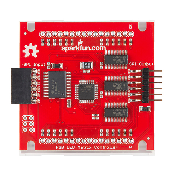
Please note that these boards have been revised and now have a separate SPI input & output on the back, which allows for easy daisy-chaining of modules.
Even more exciting - they have updated firmware and use a bit encoding scheme to control the color, allowing for up to 196 colors (3x3x2 bits R/G/B, respectively).
Are there any plans to update the data sheet, or provide sample code for this new firmware?
Oh man, I hate writing datasheets! But you're right; we've updated the code and made the SPI interface and display code much faster.
I will start working on a new datasheet and post some sample code soon.
These are a lot of fun!
http://flickr.com/photos/22886197@N00/3156366100/