- Home
- Product Categories
- Button
- Button Pad 4x4 - Breakout PCB

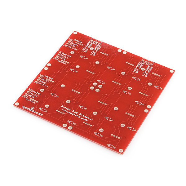
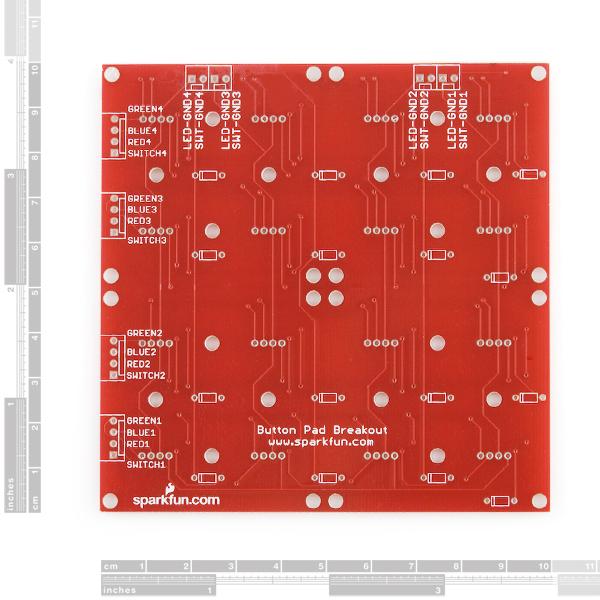
This a simple breakout PCB for our 4x4 silicone button pads. Each LED and button can brought out to the side connectors. The connectors are soldered to the back side of the PCB. We recommend trimming the connector leads on the button side as short as possible to reduce the deflection of the pad.
Now with footprints for diodes! Use the super cheap 1N4148 through-hole diodes. These can be used to isolate the switches to make for a bit easier decoding.
- Schematic
- Eagle Files
- Hookup Guide
- Datasheet (CD74HC4511)
Button Pad 4x4 - Breakout PCB Product Help and Resources
Button Pad Hookup Guide
January 7, 2016
An introduction to matrix scanning, using the SparkFun 4x4 Button Pad.
Core Skill: Soldering
This skill defines how difficult the soldering is on a particular product. It might be a couple simple solder joints, or require special reflow tools.
Skill Level: Rookie - The number of pins increases, and you will have to determine polarity of components and some of the components might be a bit trickier or close together. You might need solder wick or flux.
See all skill levels
Comments
Looking for answers to technical questions?
We welcome your comments and suggestions below. However, if you are looking for solutions to technical questions please see our Technical Assistance page.
Customer Reviews
3 out of 5
Based on 3 ratings:
1 of 2 found this helpful:
Poorly Designed
This breakout board uses a matrix type control system for the LEDs and switches. It's a good way to deal with a lot of I/O, but the board has very poor scaling for LED brightness.
Also note that with this configuration, some lighting combinations are not possible, and the method used in this link will have to be used: http://www.learnerswings.com/2014/08/theory-of-controlling-diagonal-leds-of.html .
Current is shared between each row of LEDs, and that is a really bad thing when picking current-limiting resistors. Either the current will be too high and blow an LED, or the current will be too low when more LEDs are lit. This board will never be able to control the LED colors well, nor will it look good at all (which is what this button layout is for, anyway).
I'm sure that the idea behind this board was that current-limiting resistors would not be needed with internal pull-ups, but running 16 RGB LEDs (48 total LEDs) from GPIO power without some kind of driver is a really, really dumb thing to do.
If this board had resistor footprints for each LED anode, it would be worth it, but in this state, it's a waste of money. Just go and have another PCB printed, rather than find that this doesn't work, and have to print one anyway. $10 is a very high asking price for something this poorly thought out. I would only ever recommend this for projects that will always have a set number of LEDs on at a time.
Perfect for my application.
I wanted a soft button and light thing I could turn into a toy for a friend's child. The adafruit version of this is too small and only supports single color LEDs. This gives me many more options. I'm very happy with it.
Good quality but obsolete design
I got one of these a long time ago and never used it because the RGB LEDs are a pain to drive. The other day I pulled it out and rewired it for 5mm WS2812 LEDs. The LED footprints work fine, it just requires a lot of trace cuts and bodge wires. The result is excellent though; the buttons have a good feel and the colors look great. It would be better if this product was available for WS2812 LEDs instead of (or in addition to) RGB LEDs.
Hello, and thanks for your review. Changing to WS2812 LEDs is actually a really good idea and would greatly simplify this board as well as making it a lot easier to use. I'll pass your suggestion on to our engineering team!
Hello, I have been using this PCB for a while but button are not working as well as before. I have to press quite hard. I guess there is some oxidation. Or may be some wearing ? Should I clean the PCB ? The button pad ? How could I clean them efficiently ? Thanks. JS
Do you guys only have 4x4, or do you have another size? I'd really like to have 8x2, but this board won't support that.
Has anyone found/seen a tutorial for this? I can't seem to find anyone who's made a tutorial for how to set up the LED's or buttons in a matrix and program them with an Arduino-- Can anyone direct me to the proper place? Thanks in advanced!
Late, but I made a short guide here: http://oneelectricsheep.tumblr.com/post/87677322688/how-to-get-started-with-the-sparkfun-button-pads Let me know if it's not detailed enough, I haven't written very many guides before. Hope it helps someone out.
That's great! Thanks for sharing!
Check this out!. It's a tutorial about how to use the sparkfun PCB with Arduino and send MIDI. We have also developed a PCB (kind of Arduino shield). http://alvarorevuelta.net/midispositivomidi/ https://www.youtube.com/watch?v=d-NPSPzPXNo
If anyone's interested, I have a design for a 'companion' board that fits on the back of these and has space for 3 TLC5940's to drive the LED's from a serial connection with 12-bit brightness depth. The boards can be chained etc http://brendanclarke.com/2013/07/11/button-pad-sequencer-led-fade-test/
Very nicely done! :)
What type of RGB LED do I need to use this?
You want to use common cathode, like these.
Thanks ! Can I use it : LED - RGB Clear Common Cathode (25 pack ?
Yes indeed! Those are actually the same ones, just in a 25 pack.
Would diffused leds work better? (eliminate the spot in the centers).
Diffused will give you a more even glow. If you are using these under the button pads though, it may dim the colors shining through a bit. I'd check the forums to see how it looks if anyone else has tried that.
can i use this as just push buttons?
This is correct. To have red-red-blue-blue you have to enable Row1 red and then enable Column1 and Column2 GND only. Then you'd have to enable Row1 blue and Column3 and Column4 GND. This is not a very efficient method especially for LEDs as the maximum duty cycle was just reduced to 50% for every LED on that row. It is then further reduced if any time is spent serially updating the other rows. If each row/column can be scanned simultaneously, e.g. with a shift register, then you are better off but still at 50%. Add in the third color and you've just reduced it to 33%.
After the suggestions the board worked fine. Thanks for the help, hope they are useful to future people working with this board.
Love this!
Some observations... I had a hell of a time with this board. Tested every single led before soldering them, and almost the entire first row would not light up on green or blue, never to mind the fact that clearly I got an older board with mislabeled green and blue, however that was easy enough to deal with.
The fact that partway down each blue and green lead there were breaks that I had to bridge with wire all down the first row was a headache. Not the end of the world, but still a gotcha that it's worth mentioning to someone else having trouble. I note that someone else in the comments had a similar problem. I'm glad I didn't clip my LED pins after soldering until I'd tested each and every single color on each LED. I still had something to solder wires onto to compensate.
I also have noticed like others that there is some sensitivity to static with the button pads. So if designing a circut for these buttons, I would recommend filtering noise with a couple caps.
If you're hading trouble with the blue or green pins on the first row (or bottom row), you can bridge them back to the headers with a bit of wire.
Check this out!. It's a tutorial about how to use the sparkfun PCB with Arduino and send MIDI. We have also developed a PCB (kind of Arduino shield). http://alvarorevuelta.net/midispositivomidi/ https://www.youtube.com/watch?v=d-NPSPzPXNo
I have just started a github MPLABX project using a 24F as a secondary processor to control this board. It is a work in progress, but I have some time off after the 4th. The theory is that the 24F will expose a pin to the main CPU as a signal that a button has been debounced. The main CPU will communicate via SPI to the slave to set LEDs, leg brightness, and read the switch states.
some will not like it because it is object oriented, but you get what you pay for (free) the url https://github.com/UriRedDog/ButtonPad.X
I have no idea when it will be finished, but if someone wants to design or code the SPI interface, then have at it. The SPI interface does not have to be OOPs, but it has to be "clean code" so that one can read it and maintain it.
Next rev of the board should have an optional 2N7000 placed on the LED_GND[1-4]. This is useful to rapidly cycle through the LED columns to reduce total current I don't know of many controllers that can sink many ma of current. And it would be useful to have optional series resistors because no RGB led has the same luminosity, forward voltage, current specs for each color. I'll be doing an ARM SPI driver with MCP23S08 (switches) and MCP23S17 (or 74lv154) for LED. Has anyone measured the debounce interval yet?
Hi, I think it is quite obvious but anyway i haven't seen it written anywhere: These are sensible Switches right? I mean, not just two output values but an analog range.
Thanks!
Could I break this in half to make a 2x8 panel?
Hi everyone, Can I use this with common annode RGB leds? Looking at the Eagle file it looks like there are separate GNDs for LEDs and switches but not 100% sure! Thanks!
Hey I'm a bit confused, if I want to control each LED's color and brightness individually (ie "analog") via an arduino how do I set up the resistors with the matrix? I understand in principal how the matrix works from reading the linked article, and it makes sense for the switches, but I want to do more than binary on/off for the LED's.
I got the breakout boards for the TLC5940, I would just control the LED's individually in that case right? (ie switches connected to the matrix pads on the outside of the board, and the LED's connected directly from the board)
is it possible to use common anode LED's on this board?
Hi there! Did you find out whether it's posible to use common anode LEDs?? I am trying to use tlc5940 to control multiple PWMs and there is a handy Arduino library that seems to require common anode! [http://playground.arduino.cc/learning/TLC5940] Thanks for any help
Has anyone experience the same kind of trouble?? I am able to control every led except the 4 wired to LEDGnd4. So i presumed one of my solder or wiring was wrong but when i test: all the LEDS (SINGLE COLOUR) anode are connected to each other, same for the cathode. One is wired to the ground correctly ( exact same configuration as for other LEDGndX ). i'm sure my leds are connected properly and my testings are the same for every LedGnd. Could it be a manufacturing problem inside the circuit??
I also have a few problem to figure out how to detect the button pressed. The only solution i came up with is: putting all the "SWITCH" (rows) to +3,3 or 5v. And do some digital reading on the SWITCH GND. When a SWITCH GND is detected as HIGH, it means a certain column has been pressed. But unfortunately we miss the row information this way. How are we suppose to handle the "switch" pins and the "switch gnd" at the same time?
can i connect this to a brain jr from livid instruments so i can add mode buttons to the brain? what i want is to put a 4x4 button pad with rgb leds on the breakout pcb and connect that to the brain jr. on the brain i can connect more buttons, potentiometers, encoders and leds can the brain jr handle this??? if it can, how can i connect them both?? brain jr http://shop.lividinstruments.com/brain-jr/
can i connect this into a brain jr from livid instruments?? i want to use this breakout PCB for some LED compatable 4X4 button pads and RGB LEDs for each button then i want to connect this to the brain jr so i can connect even more buttons, some potentiometers and more RGB LEDs. can the brain jr handle this??? if so how do i do it??
brain jr http://shop.lividinstruments.com/brain-jr/
I'm using this with these LEDs: https://www.sparkfun.com/products/9264. However, the holes in the PCB are spaced farther apart than the leads are on the LED... Does anyone have any suggestions to get the LED flush with the board? I didn't push very hard, but at the closest I could get the LED down to the board, the button pad still hits the LED.
i pushed the LEDs in as far as I dared - they were about 1/8 inch above the board - and the buttons didn't hit them. hope you were able to figure it out!
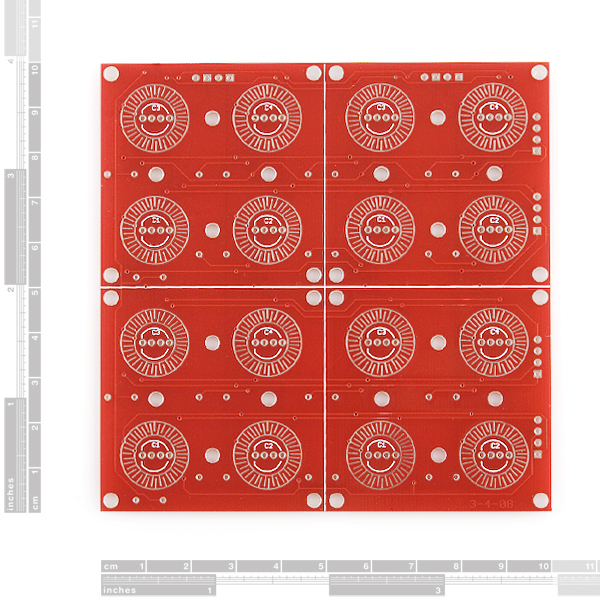
Hi, sorry for my english. I have a question: what are the circles around the four holes of RGB-LED? They seem made of conducting material. Thanks for help
That is exactly right! This product can be used with (Button Pad 4x4 - LED Compatible)[https://www.sparkfun.com/products/7835], which is a translucent silicon rubber button pad which, if you check the pictures there, has rings of a conductive material (similar to those in a typical remote control or even many modern laptops). When that conductive material touches both parts of the ring you identified (if you look closely, you'll see that it's two rings, interleaving), that can be detected as a significant drop in resistance :)
Thank you very much! In fact firstly I was looking for a button pad and I found out that button pad 4x4 that you speak about, but I needed a PCB and I found that; now I want to use that two products together. So I can use that ring as a switch?
The ring, combined with the conductive surfacing (the black stuff) on the silicone rubber 'buttons', are what forms the switch. Keep in mind that it is a momentary switch, of course; a button, not a toggle :)
If you want to know how to interface with it, check out: Using Sparkfun's 2x2 RGB LED Button Pad with an Arduino. The same concepts apply to the 4x4. The site is a little slow to respond, but the code Aaron gives there simply uses digitalRead for the buttons :)
Hi is the tutorial you posted still available (for using 2x2 RGB LED Button Pad with Arduino)? The link isn't working...
Thanks
I'm afraid I didn't save it, myself - and the internet wayback machine/archive isn't finding anything too useful (just text) either. You may try contacting the author, or see if the website comes back up, or try the archive anyway - the sketch links should give you some idea, at least :)
thanks for the quick reply!! You might be able to quash a few of my worries anyway. I've bought the 2x2 breakout PCB and the 2x2 button pad. I have 4 rgb leds, and the diodes i might need. I want to use just arduino (no extra hardware, like a digiPot) to control the whole setup. Is that possible? I don't fully understand the use of the breakout pcb yet, since their schematic isnt up, and i cant find a decent tutorial, but it seems like it uses all kinds of extra components and funky ways of determining button presses. Why cant i just treat each button like a standard push button and control each RGB LED leg with analogWrite?
Thanks again! Joni
Hi! I decided to post a reply in the 2x2 Button Board comments thread, since that's the actual board you have. Just as a quick reply to your specific questions here: You certainly can! The only bit you have to keep in mind is the shared common pins for each color for all 4 LEDs, requiring you to do some multiplexing for complex control over each individual LED.
Can you read the mind of persons? :) My project is to use that button pad with Arduino for made something how a drum machine! Thank you for the help and for the site; and what about the voltage? What's the true voltage to use with that device? What's the maximum current that can flow in it?
hah, that would be convenient - and probably very disturbing...
Since this is just a board I could cite some crazy voltages and currents, but basically it breaks down to:
1. The button pads of choice (e.g. those silicon rubber things). I'm sure they have a maximum current rating, but since the intended use is just as a switch, jut wiring the board's button pads up as you would any other switch should be fine.
2. The LEDs. This will depend on your LEDs (check datasheet) and how you end up wiring things to the Arduino (keep in mind the Arduino may have a per-pin maximum current and an overall device maximum current - check datasheet!).
That's getting outside the realm of this particular product, the board, though :)
Thank you for help! I realy want to test that product with Arduino
What type of diodes do I need to use this?
1N4148, as stated in the description
I need a 4x2 keypad. Can I cut this in half? Someone else asked this but there was no response.
Also wondering about dimensions and connectors - I'm using Altium designer and I can't import Eagle files.
You should be able to cut this in half - either horizontally or vertically, but horizontally makes more sense (vertically you'd end up cutting through resistors, horizontally you 'just' have a trace to avoid). Keep in mind that the other half becomes a bit of a pain to work with because it doesn't have the connectors for either the column or the row (depending on how you cut). Unless you're trying to save money badly (the pricing is nowhere near linear, admittedly), why not get the COM-02977 ( https://www.sparkfun.com/products/9277 ) instead? That's a 2x2 - get 2 and you can easily have a 4x2.
As far as dimensions go, the board is 100mm x 100mm and is subdivided in 4 50x50mm segments with the button pad and LED pads centered on further 25mm x 25mm quadrants for each segment. The mounting holes between the pads are aligned with those pads and the dividing lines for each quadrant, while the mounting holes in the corners are 2.5mm out from the edges of each segment. All the mounting holes are 3mm diameter. The headers are 0.1" pitch.
Can I use this for a simple push button pad? I'd like to use for simple on/off project, no microcontroller.
Just to be clear: I can cut this to make two 2x4 boards, correct?
Anyone know a decent way to get to the output pins, like a little header board or some such?
It would be nice if the sets of output pins were on the same 0.1" grid, so that I could put a piece of perfboard underneath this and have all of the outputs line up properly.
Any chance of getting a 1x4 board? I have several projects that need linear rows of buttons (vs. matrix). I would love to use these nifty lighted buttons, but it doesn't look like this board will work if sliced 1x4.
Does this pad essentially work on the row/column concept of the telephone style keypad?
I think I understand the switch and LED matrix. But if I understand correctly, if I turn on Red (for example) on the top row, then red will be on for all 4 columns on the top row. In other words, I can't have the top row be red, red, blue, blue. Instead it would be red, red, purple, purple. Is this correct?
This does not work well. Been testing this for use in my senior project with the 16 button pad and frusterated to find it is HIGHLY affected by static. Simply placing my hand near the buttons is enough to connect any of the white circular connecters. I am trying different methods of solving this so far with nothing working exceptionally well.
i also had a lot of false positive readings - i put some 1k external pull-down resistors on the digital inputs of my arduino, and that fixed the problem!
Make sure you're using pull-up resistors on the buttons, they are not included on the board. You can do this either by modifying they hardware or by using internal pull-ups on the microcontroller you're using. The internal pull-ups is by far the easier option.
Without the pull-ups on the button, they will not work very well. I don't know why putting your finger in front of the button makes the "connection," but I've seen the same result when I don't use pull-ups.
Hmm - this is the first problem with static we've heard. You must have a very large static build up to cause a switch closure.
Hi
Is there a board that will fit on under this board to bring all the pins to one side and also make it easier to control
Thanks
Maybe i'm a bit retarded, but if on the RGB LED, the pins are (common cathode): R, GND, G, B? Then, why the fuck the pcb order is R, B, GND, G, so you have to twist the LED pins if you want to follow the pcb, and then, the button doesn´t push correctly. Or ignore the pcb writings, and put the damn LED in the normal way, and reassign the pcb pins? it's part of the spark-FUN?? (ha ha ha).
As per the RGB LED:
So basically they had RcBG LEDs before, which this board was designed for, and later LEDs were RcGB. Thankfully, yes, you can just ignore the silk screen labeling, as long as the common pin is still the same one :) While annoying, it would be a waste to throw the boards out. I'd guess a future revision will have the silkscreen modified to match the new LEDs, or simply made agnostic (in case they end up getting BcGR LEDs at some point).