- Home
- Product Categories
- XBee Boards
- Breakout Board for XBee Module

Breakout Board for XBee Module
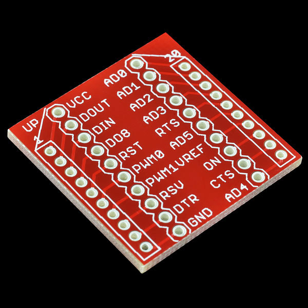
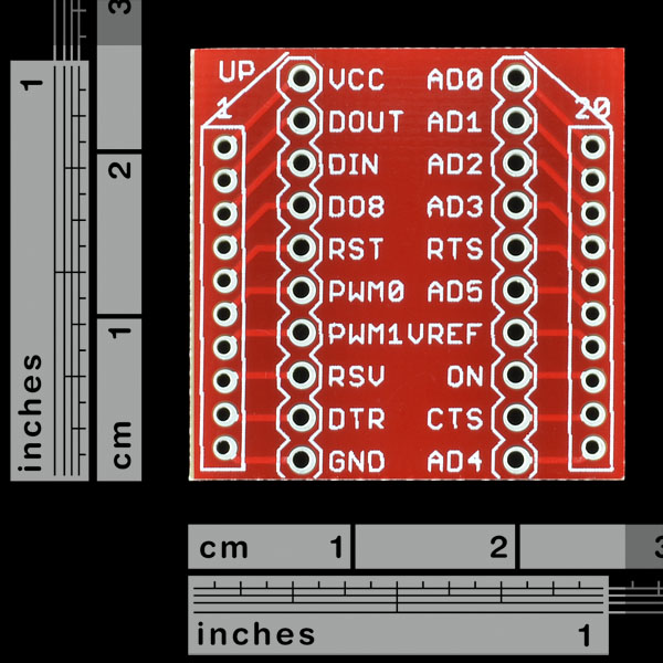
This is a simple breakout board for the popular XBee product from Digi. This board breaks out all 20 pins of the XBee to a 0.1" standard spacing dual row header. The spacing between 0.1" headers is 0.5" making it breadboard DIP friendly. We highly recommend using the female sockets to avoid having to solder the XBee permanently to the breakout board. This is the PCB only. Please order the accompanying 2mm sockets (you'll need 2!) and 0.1" headers below.
- Schematic
- Eagle Files
- 5V Interface to 3V XBee module
- X-CTU Software
- GitHub (Design Files)
Breakout Board for XBee Module Product Help and Resources
Exploring XBees and XCTU
March 12, 2015
How to set up an XBee using your computer, the X-CTU software, and an XBee Explorer interface board.
Core Skill: Soldering
This skill defines how difficult the soldering is on a particular product. It might be a couple simple solder joints, or require special reflow tools.
Skill Level: Noob - Some basic soldering is required, but it is limited to a just a few pins, basic through-hole soldering, and couple (if any) polarized components. A basic soldering iron is all you should need.
See all skill levels
Comments
Looking for answers to technical questions?
We welcome your comments and suggestions below. However, if you are looking for solutions to technical questions please see our Technical Assistance page.
Customer Reviews
5 out of 5
Based on 2 ratings:
2 of 2 found this helpful:
Handy
I used two of these back to back so I could hijack the TX and RX signals and run leads out to a couple of digital input pins on my Arduino. Very handy for testing as I can now talk to the GPS Bee and send output to the serial monitor on my PC simultaneously.
Good stuff
Makes working with Xbee's fun!
I read these comments, and thought to myself, "I'm going to screw this up", especially since I've just started to learn how to solder. I was surprised after wards (having soldered in both the headers and the 2mm sockets) that every thing connected just fine, and continuity testing with a DMM confirmed that all the connections were made. I do admit that I did error on the side of too-little solder and therefore some of the joints may not be as strong as they should be, but I suspect it will be fine.
Congrats on the soldering success!!!
a good idea for anyone reading this is to tack-solder all headers in place, then go back and finish the job properly.
or u can put the pin headers in a breadboard, place the P.C.B. on the headers and solder it in the breadboard.
Just be careful not to overheat the plastic in said breadboard and melt the plastic onto the pins :)
Is there an EAGLE-File of this somewhere?
Be careful soldering in the stand offs! Don't let too much solder run down into the holes.
I soldered in the 2mm sockets normally, and some of the solder ran through and into the holes that accept the xbee's pins. I could not get the solder out with wick, so the socket (and the board when i tried to desolder it) was ruined.
picture here:
http://picasaweb.google.com/marc.bayerkohler/Misc#5256440319164643730
you can see where some of the solder went through and filled the copper receptacles, so the xbee would not plug in.
I second this. It's not my first time soldering. It's also pretty common to solder headers on top of components to make sure that they align properly. The problem with the 2mm headers is that the solder can flow from the pad and pin to the actual socket side of things.
This happens regardless of whether you solder things without the XBee attached, I just soldered together another of these things and the XBee wll not sit completely flush because of this problem. I'm not sure if this is just the nature of 2mm headers, my XBee explorer doesn't seem to have this problem, but it's sub-optimal to say the least.
Of course, this is more of a comment for the 2mm female headers than the BOB. Still I feed pretty dissastisfied with the overall expereince.
You know I was really careful about heeding your advice. I used my Xbee pro to hold the headers in the right position then tacked them in place using only a small amount of solder. Unfortunately the solder still ran down the terminals and soldered the Xbee to the headers on one pin. With a little extra heat from the soldering iron and a small flat blade screwdriver I managed to remove the Xbee but still damaged it, not sure if it works yet. The other two boards I had to do I didn't push the Xbee so far into the sockets, the result, no problem. Lesson to be learnt, if you are going to use another part to space headers don't push it all the way in.
It's clearly a problem, I think that at the very least, these things should ship with a big fat warning about soldering the 2mm headers. XBees are not cheap.
Is it me, or should these boards also have the outputs listed on the other side of the board as well?
I really with that these boards had the female ports pre-soldered into place. I have already kinda killed one set, half the board plugs in fine, the other side will not push in completely. I have tried to reheat in hopes that the solder would flow back down, but no dice. I am thinking it is time to get a de-soldering wand that is built onto a soldering iron. I will try not to kill the second one and solder it upside down in hopes that it will work better. Also, time to use a hair of flux. My soldering iron is using a really fine tip too, I tried not to flow too much solder in.
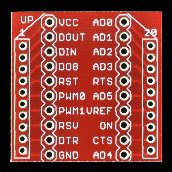
Honestly, The only issue I see with this BOB is the fact that the screenprint is on the top of the board. It should be on the bottom and reversed. Not that the board orientation would make any difference. It would require a new screen, But this would allow you to see the pinout of the XBee. I could see, a confusion issue. Your mind would initially want to put the XBee on top of the print, Thus why its says UP in the Upper Left Corner. But I still think it would be more logical to have it otherwise. One other feature I think would be great, Make this bare BOB more like a 5V regulated BOB. Put the G-5V-RX-TX pinout on there as well.
Totally agree. The screen isn't where it should be. You can't read the pin labels if they are under the Xbee module (so why print them in the first place), and it's inconsistent with other product, say the SFP Xbee USB Explorer.
Why isn't this available as a kit, with the board and all four headers, to order with one click for a discounted bundle price?
this is a great little board to have around. pick up the 2mm headers. they are harder to solder than .01. use a small iron tip and a sponge. solder every other one to tack them down. you can use this instead of the xbee shield with a few jumpers.
I got one of these with the Building Wireless Sensor Networks kits. Thanks to the shitty headers that ship with the kit I ended up soldering the headers onto one of my XBee. Nothing worked to unstick the components. Half an hour later of attempts and I have a totally trashed XBee breakout board and headers. All in the garbage. In retrospect I should have just let it be that way.
Now I'll be the first to man up and say that I can't really blame SparkFun for what happened. Part of the learning experience. It was silly of me not to have anticipated this. I should have let things be when i realized the darn things stuck together. But you know what would have helped: A FRIGGIN WARNING OF SOME KIND!!! Or some headers that I solate the pins in a way that this doesn't happen. For a fraction of cents the manufacturer could add enough metal to produce a header where the solder doesn't leak from the header pins to the pins of the attached XBee.
Anyway I guess I just needed to rant. I'll probably be buying my next break-out board headers and XBee from SparkFun. The hit to my ego and the sour taste in my mouth will probably take longer to deal with.
the 2mm header are much harder to solder.
To clarify: you will not need to solder the xbee to the breakout board. However you will need to solder the headers and female sockets to the breakout board. This was one of my first soldering projects, and all the pins seem to be working. Make sure you watch some tutorials and practice with your iron first! After that, I had no problems.
I can confirm it is unusually difficult to solder the 2mm headers onto this board. Compared to the 0.1" female headers SFE sells, these sockets are about half the depth, and the pins are thinner also, so there is more room for the solder to flow down into the socket. All you have to do is screw up one of the 20 solder joints to make it difficult to seat the XBee module. I just ruined by BOB. SFE: you could be doing us a HUGE favor by providing this board. with pre-soldered headers, at least for the 2mm pins. The rationale for NOT providing pre-soldered connectors is always to provide "more flexibility" but that doesn't apply to this BOB since the only point is to connect an XBee module (which comes with its own pins.
Im like realy new to this kind of stuff and i want to connect a video camera to the xbee pro900 but i don know how. Please i need help
Unfortunately no XBee has the speed or connection for live video. But there are wireless cameras you can buy elsewhere that will do what you want.
Hello everyone, a newbie question, if i use this breakout board for the XBee module with the recommended sockets do i still need to solder anything? Can this board work without any solder? Sorry if the question is too stupid but im new in this kind of things. Thank you for your time.
If Sparkfun highly recommends not soldering the XBee to the base, why is there is much concern about soldering the XBee to the base? Does the base make poor contact without soldering?
Love these things! Thanks Sparkfun! (Yes, I did ruin a few of the smaller 2mm sockets. But live and learn: 389654's "3 second technique" is the way to go).
I bought a bunch of these breakout boards, an Xbee Explorer USB and several AdaFruit serial-to-XBee kits. I learned the hard way about how solder and these headers/XBee don't get along; I actually soldered one XBee into the header, not realizing the amount of solder flow I was getting.
I found a slightly different technique than those mentioned here. It is similar to those I've seen for easy surface mount soldering:
Once I figured out the "right way" to do this, it became trivial to get an XBee socket soldered like a pro.
NEVER NEVER try to solder a joint by putting a blob of solder on the tip of the iron, goes against all accepted practices and can result in cold or poor solder joints. Here's the proper technique. First, a little flux can be used on the joint if you do not have fluxed solder but it must be non corrosive, then clean the tip of the iron on a damp sponge, then tin the tip with a bit of solder and wipe clean again. Touch the tip to the pin and the thru-hole or pad so it touches both, then take a piece of thin solder and touch it to the joint on the opposite side from of the tip. If the tip is hot enough, The solder will melt almost instantly and the heat will draw the solder into the joint. Then quickly remove tip. Should be about a 3 second process. If this doesn't work, the solder won't melt, then your iron is too small or the solder is too big.
For all the people having trouble soldering these together, try this! (My first time was a failure, so I decided to try a new method, and it worked awesome!)
1) Get something to hold the board, header pins, and xbee. I use helping hands from harbor freight http://www.harborfreight.com/helping-hands-319.html
2) Put the header pins on the xbee, and orient it into the breakout board however you wish it to be soldered.
3) Using one of the alligator clips on the helping hands, grab the breakout board and hold it in place parallel to the ground (with the xbee on top!). This way the weight of the xbee is holding the header pins into the breakout board.
4) Get BELOW the board with your solder gun. Apply a small amount of flux to the pins to get good solder flow. Now, solder the four corners down. You'll want to have a decent tip to solder these properly. Once you have soldered the four corners, remove the xbee and solder the rest of the pins.
You still will want to use a minimal amount of solder even when doing this. I found it helpful to push against the header pin when I was heating it to solder, and just touching the pad enough to heat it. After you are done, make sure to continuity test and check the solder joints. You can always go back and add more solder.
Good luck!
Can someone help me understand why the 3.3V can't be created with simply one LDV33? Seems there's an awful lot of soldering, resistors and LEDs going on to just shift the voltage from whatever (5V) to 3.3V.
I'm sure I am missing something, and that the "3.3v 100ma regulator" is needed, but I have no idea what that is
Tip for anyone buying this: buy extra headers. I read all these comments and still managed to screw this up. The worst part is knowing that you can't really fix the problem like you can with most soldering errors. Idea for any expert solder masters out there: sell these pre-soldered and make a killing ... like SparkFun should do in the first place.
Didn't have any issues soldering three boards and associated headers. Used .031", 63/37 solder, iron at about 720°...placed a little dab of solder on the tip, touched it to the pin and then barely touched the pin with a separate piece of solder. Checked the joints with a magnifying glass and touched up any that were suspect.
is there any particular reason i couldn't just solder the xbee module to the break out board? no headers, just solder it in. i'm trying to keep my project as thin as possible.
The only reason most people don't solder directly into the board is because it limits your ability to troubleshoot the Xbee, or remove and reprogram it easily if needed. However, it will still work if you solder directly to the board.
When is this likely to get back in stock?
Thanks, Hayes.
February 11, as I was told. Keep waiting, almost there! :D
Still (or again?) not in stock... Would be really nice to have soon...
It's been delayed but they have been shipped and we're getting a LOT of them. Give it a little bit more time.
Am I nuts? I ordered the headers and sockets listed on the product page for the breakout board. The sockets are right; the XBee will clearly fit properly.
But the headers that would plug into breadboard are not spaced properly. They are plainly spaced at 2mm like the sockets instead of 0.1".
What's the deal? Me? You? Can I get the right headers please?
Tnx
I did the same thing as you. Apparently what we were looking for is the "Break Away Headers - Straight" and not the "2mm 10pin XBee Header". I'm glad to know I'm not the only one who was confused though (especially since I'm still not exactly sure what the XBee Header is for then) but it is confusing when the XBee Header the 4th "related product" and right below the XBee Socket that you actually do need.
So, for anyone else that wants to use this in a breadboard, make sure you grab 2 of the "2mm 10pin XBee Socket" and just one of the "Break Away Headers - Straight" (it's twice as much as you need) BUT NOT the "2mm 10pin XBee header".
I guess this is called learning experiences + $9 shipping. :)
To avoid solder propagating into the 2mm socket, some can glue two strips of capton tape on the component side beneath the socket strips and punch small holes for the connector pins.
It is easy to do two things with this board:
1) Solder correctly and get no solder into the connector
-or-
2) Solder incorrectly and get solder into the connector
Thanks to those who pointed out that it takes some care. I just soldered mine with no problems. Here's what I did to make it work: First, I used a bit of flux. I rarely add flux to things I'm soldering unless I think it may really need it. This doesn't need it but I added it just to be sure.
Second, I would estimate that I held my soldering iron tip on any given connection for about 500ms maximum. And I use a hot tip - 720F. The idea is heat it quickly, apply solder, remove heat when the solder flows. A small, low thermal mass tip running at 600F takes a long time to melt the solder. This allows the ENTIRE socket pin to heat up and readily allow the solder to flow where you don't want it.
It takes practice but is easy enough. One last thing: inspect your solder joints carefully with a magnifying glass; I had one cold solder joint out of 20 pins. A quick reflow fixed that.
I am yet another victim of this soldering problem. I wish I had read everyones advice first.
Maybe soldering the board upside down or sideways would help. A bit of tape to hold the connector and the board in a vice or similar.
Ahhh yes, finally success.... these don't have the same pin-outs as the regulated xbee I also ordered. The ground's are on opposite sides of the board. There goes any ability to easily swap between the two in projects on breadboards.
hey so which one should I buy .. this or regulated xbee breakout board..I dont wnt to complicate things much.. I just want my xbees to work...
Depends on your circuit. The Explorer regulated board does the voltage regulation and logic level conversion so if you don't need those and want to solder the headers on get this one, otherwise get the explorer regulated.
I had the same problem with the solder going into the socket. Took me ages to persuade the solder to come back down the pin out of the socket. Maybe a mention should be made on the product page about this?
I realise now that all that solder must have been going somewhere! At the time though I just kept pumping it in.
I read the comments on here before attempting to soler the stand-offs and STILL managed to ruin one on my boards in in the same way. Sparkfun need to start selling these pre-soldered. What a waste of money :(
The Regulated Xbee Eplorer is presoldered with headers, but they are a little bit more expensive because they also allow a 5 volt power supply to be connected.
Funny, I had the same exact problem while soldering the 2mm sockets to this board. Only I took it a step further, and ruined two boards in the same fashion, as I didn't check out the first board before starting on the second.
I had the same problem, but was lucky enough to be able to use the side with that has the serial and power connections.
Maybe Sparkfun could carry some of these with the Xbee sockets already soldered on?