- Home
- Product Categories
- Power Supply
- SparkFun Breadboard Power Supply USB - 5V/3.3V

SparkFun Breadboard Power Supply USB - 5V/3.3V
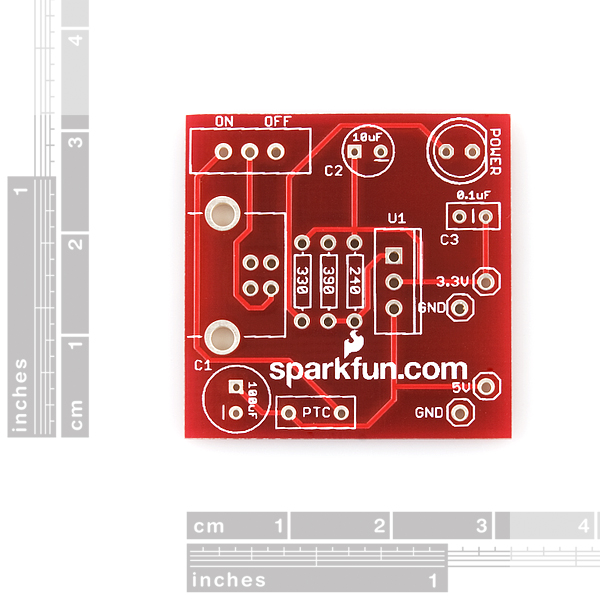
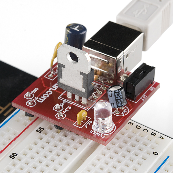
A very simple breadboard power supply kit that takes power from any USB port and outputs a fuse protected and regulated 3.3V. The .1" headers are mounted on the bottom of the PCB for simple insertion into a breadboard. Pins labeled 5V/GND 3.3V/GND plug directly into the power lines.
When you plug this board into a breadboard you must be aware that the unused power and ground pins will short if they are inserted into a bread board row. To avoid this problem, orient the board so that the unused power pins are left off the side of the breadboard. You can also orient the board sideways and utilize both 5V and 3.3V at the same time.
USB v2.0 specifies a max of 500mA at 5V. The on-board fuse limits the current to 500mA. Board has a handy On/Off switch.
Comes as a bag of parts kit and is easily assembled if you can follow the silkscreen indicators and have beginning experience with a soldering iron. You will need to read the resistor bands or use a multimeter to determine the resistor sizes.
Check out our Unregulated Power Supply Tutorial!
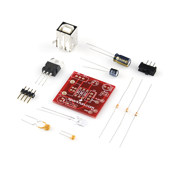
Kit Contains:
- USB type B connector
- TO-220 Voltage Regulator (LM317 1.5A max current)
- PTC Resettable Fuse
- 100uF 35V Capacitor
- 10uF 25V Capacitor
- 0.1uF 50V Capacitor
- Power LED
- SPDT Slide Switch
- 4pcs 0.1" Header Pins
- 330 Resistor 1/6W
- 390 Resistor 1/6W
- 240 Resistor 1/6W
- Bare PCB with Silkscreen Indicators
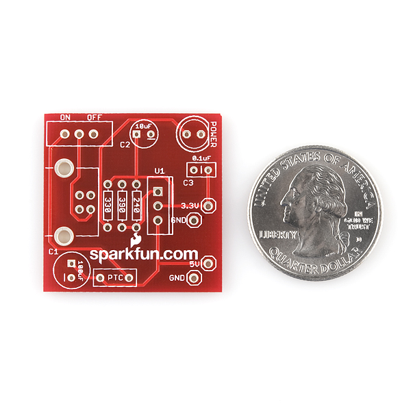
- 1.25x1.25"
SparkFun Breadboard Power Supply USB - 5V/3.3V Product Help and Resources
How to Use a Breadboard
May 14, 2013
Welcome to the wonderful world of breadboards. Here we will learn what a breadboard is and how to use one to build your very first circuit.
Core Skill: Soldering
This skill defines how difficult the soldering is on a particular product. It might be a couple simple solder joints, or require special reflow tools.
Skill Level: Rookie - The number of pins increases, and you will have to determine polarity of components and some of the components might be a bit trickier or close together. You might need solder wick or flux.
See all skill levels
Core Skill: Electrical Prototyping
If it requires power, you need to know how much, what all the pins do, and how to hook it up. You may need to reference datasheets, schematics, and know the ins and outs of electronics.
Skill Level: Rookie - You may be required to know a bit more about the component, such as orientation, or how to hook it up, in addition to power requirements. You will need to understand polarized components.
See all skill levels
Comments
Looking for answers to technical questions?
We welcome your comments and suggestions below. However, if you are looking for solutions to technical questions please see our Technical Assistance page.
Customer Reviews
4 out of 5
Based on 2 ratings:
1 of 3 found this helpful:
For somebody who want to have a fun
made a mistake by buying unsoldered version (they have a soldered one). now I need to spend time to read resistor bands, find where to place them, solder, etc... Thought it will be fun, but it just do not worth time... Next time will buy a ready to go one :-) Moreover I found that I do not need this particular board, what I thought when I was buying it, I do not know... The rest is good, received it on time, all parts are in bags, just need some time to make it ready...
In the description above it says the PTC limits current to 500ma; however, the PTC listed in the related products below says it limits current to 250ma on the product page. Can you confirm that the PTC sent with this kit is actually a 500ma PTC and not the one below?
I ordered 5 of these, before they changed the picture to show the new design (red board). Like ISR, I was confused and amused by the offset output pins, but after a quick note to tech support asking why in the world it changed, they refunded the cost of all 5 back to me. I pointed out that I was still going to use them, just needed to get some extra parts I didn't know I was going to need, and they said no problem, they'd refund them anyway because it wasn't what I thought I was getting. Now THAT is customer service. Wow!!
Out of the 6 kits I have in total, none were missing the LED, but one had an extra 240 ohm resistor and was missing the 390. No problem- customer service sent me a 390! I know, a lot of work for a 2 cent resistor, but all I had lying around in that range was 1/8th watt.
I was wondering if it would be possible to exchange the USB type B connector for a type Mini-B connector before ordering.
I have one of these and it does work well, hooray :)
However I wonder if an LDO should be used instead of an LM317 - especially at higher currents the dropout is quite high (>1.5V).
A LD1117V33 has a maximum dropout of 1.2V.
You can do this yourself if you remove R1 and replace R2 with a link (for the 3.3V fixed version).
I am interested on this "USB 5V/3.3V" power supply. It can be convenient in some situation. But I am wondering if this circuit can reach its announcement, a 500mA max current? According to the specification, a USB 2.0 port, when in the unconnected status, can only supply 100mA max current, before the device requests for more. I check its schematic and the D-/D+ pins are left open, which means that there will be no device appears to the USB port. This power supply seems can only supply a 100mA max current. Am I worng?
This might be too late, and I didn't test it myself (although I'm building a circuit like this, will update the reply when I test it myself.
I've read that the 100mA limit is working only if a device is connected to the USB port. If you leave D-/+ pins disconnected, the port thinks there is no device, so it doesn't bother limiting the current to 100mA (but surprisingly power is available anyways.)
I'm definitely way too late, but for the benefit of anyone who wanders through...
As I understand it, most desktop PCs just wire up the USB 5V line to the power supply's 5V line with minimal stuff in between since circuitry costs money and the PSU's got plenty of power to spare.
It's the laptops (which are designed to manage battery life) that you've gotta watch out for. They usually DO have the circuitry to limit devices to their current allocation and, while I don't have a laptop and a power-heavy USB doodad to test with, I'm told the usual reaction to attempting to draw too much out of a laptop is for the supply to be cut off entirely.
Just so you all know, the LED in the picture above is oriented incorrectly. Make sure you check out the wikipedia article and scroll down about half way to see how LED's are oriented with regards to a printed circuit board. http://en.wikipedia.org/wiki/LED_circuit
Is there a reason why I can't /shouldn't just take the two power lines from a USB cord and stick those in my breadboard with various voltage dividers and/or current limiting resistors? I want to build small projects powered by USB, and this seems to be a bit overkill for a couple leds.... EDIT: Never mind. My knowledge has increased since I asked that and now I know that I could.
Any chance we'll see a kit that lets us use USB3's theoretical 900mA?
Heck, if it'd be possible to place a "like" on this product, I'd do that. Awesome little kit. I've enjoyed soldering it very much, also worked OK from the first power-on. Yummy!
Since you can't solder a 0.1" two pin header into the staggered 3.3 and 5v power and ground pins, what I did was cut off six pins of a double row break away header, and then remove the eight pins that don't correspond to the holes. This left four pins that fit perfectly into the board. Unfortunately I don't think SparkFun sells 0.1" double row break away headers (too bad, they should, they're handy to have around). But you could probably use two rows of single row headers instead.
That link has gone all 404. This one is probably about the same thing... (6.1 exists anyway, and has a drawing.)
http://www.ftdichip.com/Documents/DataSheets/DS_FT232R.pdf
Now they have change it to this link:
http://www.ftdichip.com/Support/Documents/DataSheets/ICs/DS_FT232R.pdf
I'm not using these in a breadboard, but in a project for powering an RFID reader/writer and an xbee radio. The RFID is 5v, the xbee needs <= 3.3v so this board is a great little thing to get power from any handy USB port.
To deal with the diagonal output hole placement, I used some pins (2x6) with all the extra pins cut out of the way so I can just plug on to it with a 2x6 plug. (the plug/housing is part number 87456-8 by Tyco, the receptacles are Tyco part 1-104480-5, and you don't need the $1200 tool to crimp them onto your wires, just use needlenose pliers!) The double row pins I used are part number 5-146308-8 -- this is actually 16 (2x8) pins because 12 is about impossible to get hold of. They are the breakaway design, so i just broke off the last 4 pins to make it 12, and then did a bunch of chopping for the pins that wouldn't have any place to land on the board. SFE doesn't sell any of these part numbers, but I'm sure you can figure out where to get them from. :)
FCI makes parts to do this with too. They are cheaper, but they are really hard to crimp, and they don't connect as well.
I just purchased this kit and now I'm trying to put it together. I have to admit that I'm not very good at following the silkscreen indicators. Is there a picture of a completed board someplace? Or can someone provide some brief instructions?
I'm very new to soldering and such... and yes as @ISR said, I was also missing a power LED. I have plenty LEDs laying around though, so I'm not worried about it..
I'm a bit confused as to how the header pins are to go on this PCB though. Are you suppose to put the pin through the bottom so that the plastic sits on the bottom and you solder it from the top of the PCB(where all of the components are)?
Yea, after googling for similar PCB kits, you do solder the pins in from the top incase anyone else is wondering. It might not seem right, but it is...
I ordered one of these. The kit came without the power LED. The GND holes for the 0.1" header pins are at a diagonal to the 5V and 3.3V header pin holes; so it's basically impossible to connect the two pairs of 0.1" headers to the board. Even if I broke them into 4 separate 0.1" headers and soldered them to the board individually, the breadboard would not accept the pins because they aren't spaced correctly. Not sure who dropped the ball on this one - well done.
SFE is usually good about replacing missing parts, so feel free to contact support via email about that. As for the pin locations, as the name of the item indicates, it is intended for use with a breadboard. The staggered pins allow easy use with breadboards in that you can power the long horizontal bus at one voltage, and the other pins could be on the shorter vertical span (and jumpered over to you other bus if you like). It can also work with only vertical spans (like on the tiny breadboard), but the board will likely cover the pins on one side, so its easiest on a board that small if you only need one voltage (but its easy to get at both voltages with any of the boards with the horizontal power busses).
Thanks for clearing that up. I just used a red LED I had lying around. No use getting a $0.25 part shipped from SFE. I soldered the headers up and it does fit in the breadboard. It is just awkward looking at it before soldering it, but it makes sense I suppose so that nothing is shorted when the supply is plugged in. One thing that worries me a little bit is that the 5V out is giving 5.14V on my multimeter. Looking at the schematic I can see that the 5V is straight from the USB cable. I guess I'll just have to be careful.
I was wondering about the Gnds on this PCB. How are they connected? Or are they?
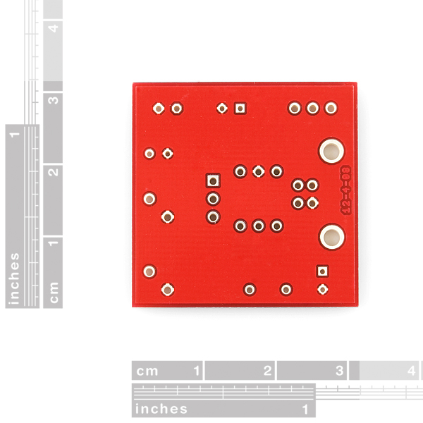
You do know that its a Double Sided PCB, I hope.
Gnd normally means ground
Just wondering how to get 5V supply from the usb ...
What kind of conditioning the VBUS needs ...
should I take this kit but remove the voltage regularot + resistors R1 and R2? i.e. create a short between the positive of C1 and C2 and remove anything in between ( reg + 2 resistors) ?
OR maybe there is a kit available for this purpose already? seems awfully useful but can't find it...
Check out 6.1 in this datasheet:
http://www.ftdichip.com/Documents/DataSheets/DS_FT232R_V202.pdf