- Home
- Product Categories
- 7-Segment
- 7-Segment Display - LED (Red)

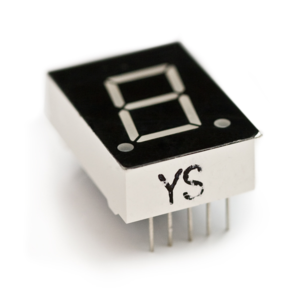
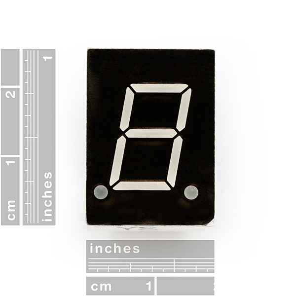
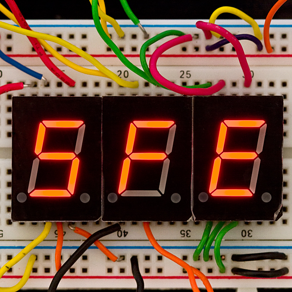
Your basic 7-segment LED. Common anode. Two decimal points, but only the one on the right is wired. Digit height is 0.6". Overall height is 1"
- Datasheet
- Arduino Library (Thanks Derek!)
7-Segment Display - LED (Red) Product Help and Resources
Beginner Parts Kit Identification Guide
March 22, 2019
The essential parts for beginning (or even experienced) hobbyists that gives you all of the basic through-hole components you will need to get started playing with embedded projects. We'll identify a few parts in the kit and provide a few basic circuits to get started!
Binary Blaster Assembly Guide
March 13, 2014
Learn how to assemble and play the Binary Blaster Game from SparkFun Electronics.
Core Skill: Electrical Prototyping
If it requires power, you need to know how much, what all the pins do, and how to hook it up. You may need to reference datasheets, schematics, and know the ins and outs of electronics.
Skill Level: Competent - You will be required to reference a datasheet or schematic to know how to use a component. Your knowledge of a datasheet will only require basic features like power requirements, pinouts, or communications type. Also, you may need a power supply that?s greater than 12V or more than 1A worth of current.
See all skill levels
Comments
Looking for answers to technical questions?
We welcome your comments and suggestions below. However, if you are looking for solutions to technical questions please see our Technical Assistance page.
Customer Reviews
5 out of 5
Based on 1 ratings:
3 of 3 found this helpful:
Nice 7-segment display
I am happy of this product that I can put easily on my breadboard. I am able to activate each individual segment and the dot (the one at the right). The luminous intensity of each LED is good. The datasheet is very useful and contains correct information about this 7-segment display. I just found a typo to fix: "Forward curret" -> "Forward current". You can connect the pin 3 or 8 to +5V but don't forget the resistor between each pin LED and the GND. You can use a 150 ohms resistor (R = (U - Uled) / I = (5 - 2) / 0.020 = 3 / 0.020 = 150 ohms).
Hey everyone! I went through the library included on this page and found that it was not working. I decided to make a new library that not only can display 0-9, but now hex numbers and a way to test your display easily with just one call. I also included a proper README with a wiring diagram and how to install/use the library. Let me know what you think.
SevenSegment Library
johngineer is correct; the datasheet pinout is wrong. This is what I've found.
Pin order looking at top of unit, right side up.
10,9,8,7,6
1,2,3,4,5
Below are the corresponding pins to each segment
(The segment notation is the same as in the datasheet)
Comon Anodes: 3 & 8
A: 7
B: 6
C: 4
D: 2
E: 1
F: 9
G: 10
DP: 5
I hope this helps.
uh this isnt correct
No, actually that's right. I can confirm this because I spent some time yesterday fixing the part in Sparkfuns Eagle library using the one I have on hand as a reference.
But Erk, onedividedbyzero used all caps so he must know what he's talking about.
obviously, right?
It's nice you edited your earlier comment so it's not in all caps, but do you still think the pinout I listed is not correct? Do you have a different pinout on your display? The pinout I listed is correct for the displays I purchased from SparkFun. Have you purchased these same displays here? Does the pinout on your display differ from what I listed?
UPDATE : Finally got around to creating a video. Hope it helps. http://youtu.be/9B5Kr3gMvZ4
NOTES : This is inspired and informed in part by user "ddegn". My feedback is specific to Arduino users who are new to seven segment displays and this product specifically. I actually ordered the blue product but this comment applies to both the red and blue so I have added in both places.
If you are new to seven segment displays and you are using an Arduino Uno with a shift register. Here are a few things I learned while using this product.
DECIMAL POINTS : 1 on the bottom right is available
CONNECTIONS TOP L-R : [ 10 / Q6 / G ] , [ 9 / Q5 / F ] , [ 8 / Power ] , [ 7 / Q0 / A ] , [ 6 / Q1 / B ]
CONNECTIONS BOTTOM L-R : [ 1 / Q4 / E ] , [ 2 / Q3 / D ] , [ 3 / Power ] , [ 4 / Q2 / C ] , [ 5 / Q7 / DecimalPoint ]
SHIFT OUT CHALLENGES : If you are reading the tutorials in the Arduino Workshop book by John Boxall you may experience some confusion when sending values to this display. The author specifies using a common CATHODE segment display. From what I understand this product is the opposite i.e. common ANODE. As a result, the matrix the author shares with you will not work. The numbers will be garbled on the display. Apparently after much research I realized that the solution is to reverse every value. In other words, to make the display work you will need to send a 0 rather than a 1 to turn on the led segment. Totally confusing until I figured this out. Also, the only way I could get my Arduino sketch to work was to add a "B" at the beginning of the value. So for example, the book states that if you want to display the number "0" on your segment you should send the following value "11111100" or the value"252." However, with this product you would actually need to send the following value "B00000011." Note the "B" at the beginning. I dont have the decimal conversion for this value you will need to research that on your own.
Hope this helps you. Took me hours to figure this out.
Thank you for this information. I am also reading the John Boxall book. I wasn't paying attention that he was using common cathode and that these are common anode.
Also,
Because of the common anode design of the 7-segment, you need to pull the pin low (set to 0) to light up a segment.
I would love to see this in common cathode, unless you can directly control these from the Arduino.
Nice item at a good price.
A complete pinout diagram would be cool, since it seems the pins don't align with the datasheet info.
So I just received four of these in the mail today (8-20-2014) and all of my previous experience was with radio shacks 7-segment displays and none others. So i plug one in and start trying to figure out which pins light which LED and one after another they start to burn out, well shit. After i realized they had indeed burned out, i also realized that these suckers are hungry for some electrons, so please BEWARE that you need a decent sized resistor connecting it to Vcc i used a 10k and the lights lit up fine. This bad boy is very bright as well, but just make sure you've got some protection so this doesn't happen to you. BTW I've never needed resistors on the radioshack LED's so it didn't cross my mind to use resistors on these displays but we live and learn i guess.
I wish the documentation was much clearer. Not, all 7 segment displays are the same. It does not suggest the pull-out resistor, or the ohms. The main picture on the breadboard is showing wires crossing the main +/- lines. There is no need for those wires. So, can you please clarify the documentation so I will not blowout another display. It is also large, and I too wish to have just a little smaller display.
Do you have to connect both anode pins? I am trying to put together a circuit board layout that holds 5 of these. Based on the datasheet diagram it looks like one could connect either anode pin and it should work.
For interfacing 7 segment with PIC microcontroller.
example code http://ibrahimlabs.blogspot.com/2013/06/this-post-is-all-about-how-tointerface.html
How many holes will this take up on my protoboard? It looks like about 7 x 9, but can I get a number?
FYI, I had no luck at all getting the Arduino libraries linked above to work. I'm not sure if anyone else tried and had the same results. After a little digging, I found some modifications posted by another contributor in the project on Github that fix the problems. Basically, it looks to me like the author just didn't have a working version of this posted. I was attempting this with Arduino IDE version 1.0.1. Post here if you're interested and I'll explain further.
Correct. I haven't tried the Pineapple library, but the Soda library has several typos and mistakes. SparkFun should probably remove the link to avoid wasting the time of people who might assume it's been tested.
Hi, I'm interested in getting the Soda library installed and working so that I can try the example code posted above. Tt's unclear what I have to press to download it from Github. Where else can I go to get this library?
Thanks, Ben
Any LED that isn't from China?
I can't figure out how to illuminate the other decimal point in this "two decimal point" 7-seg display. Can someone point me in the right direction?
"Two decimal points, but only the one on the right is wired."
Only one of the decimal places is wired up.
Ahhh. The sentence was longer than my attention span. Thank you so much!
This is a great product, with one small problem. The module is slightly oversized, i.e. when plugged into a standard 10-column breadboard, its a tight squeeze trying to get in wires.
Sparkfun, is it possible to find one that is slightly smaller?
Or is it safe to sand off about 2mm from the top?
I just got one of these to see how it worked and made a counter with my PIC18 board, am getting a couple more to make a calculator. You can find the labels in the post, I fixed them. Note that in the video I was using a 1k resistor that's why the leds aren't as bright.
How To Make a Counter With Your PIC18 Board
I'll make an Arduino example and post it here to help you get started.
I don't suppose someone has some sample AVR code to get these units lit up? I'm looking at stringing 5 of them together with 1 uC maybe an Atmega48 and use another uC to signal the first.
there is a plastic film that comes covering the face of the display. It protects the matte-finished display face underneath. It doesn't look too bad if you prefer the glossy appearance leaving it on, but after you are done soldering your dedicated project it is nice to take off the film, because it looks less tacky.
The displays are nice and bright, you could easily see it in most lighting conditions (except direct sunlight would make it difficult)
easy to plug in to your micro controller (with resistors of course) and get working.
I didn't bother trying to find a datasheet with the pinouts, i used my multimeter's diode test function (you could use the proper resistor and a power supply) and just probed the pins to see what i needed. Someone here mentioned the top and bottom middle pins are positive, and they were correct, so I went from there.
for a buck a piece you cant go wrong.
And the pinouts given by ddegn are correct.
I wonder if this unit is waterpoof? I know that it is potted, but I'm not sure if the front panel is ok to expose to the elements?
I don't know to much about programing 7segs can someone simple post some code (for an arduino) to display 3 then 2 then 1 with 1 sec delays. ill figure it out from there...
I know am replying late;I just got this product.
But for those who are getting started I've made an Arduino tutorial on this 7 segment led. It's an Automatic Counter With a One Second Delay
Thanks for the tutorial! Nice explanation, I like the hex shortcut!
Great product. The middle pin on each row is the common anode. Don't connect them to a too high voltage though or you will fry the display. I accidentally did this with one of mine by connecting it to 5V, now it's dead :(
No problem with 5V if you add a resistor between each segment PIN of the LEDs you want to activate and the GND. R = (U - Uled) / I = (5 - 2) / 0.020 = 3 / 0.020 = 150 ohms. It works on my breadboard and the datasheet is correct :)
Did you forget to use a resistor?
Where you trying for 3.3V or what?
we have a new led segment display ( Serial input-output 7-segment display) my aliexpress shop:http://www.aliexpress.com/store/113291 Company Website:www.szdree.com