- Home
- Product Categories
- Infrared
- SparkFun IR Receiver Breakout - TSOP85

SparkFun IR Receiver Breakout - TSOP85
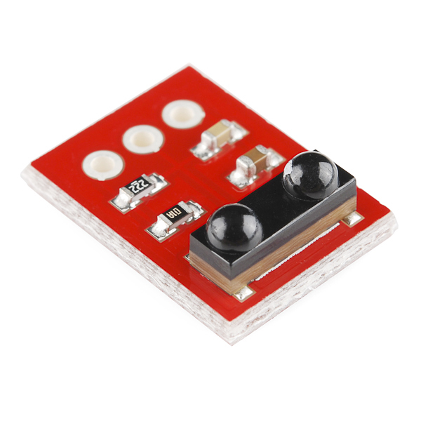
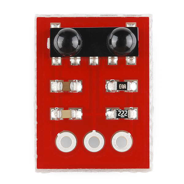
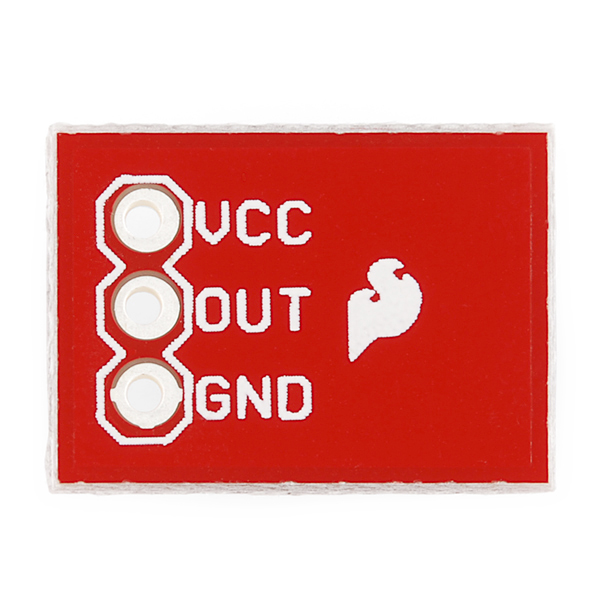
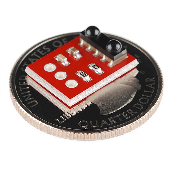
This is a very small infrared receiver based on the TSOP85 receiver from Vishay. This receiver has all the filtering and 38kHz demodulation built into the unit. Simply point a IR remote at the receiver, hit a button, and you'll see a stream of 1s and 0s out of the data pin.
SparkFun IR Receiver Breakout - TSOP85 Product Help and Resources
IR Control Kit Hookup Guide
October 2, 2013
How to get the most out of the infrared receivers and transmitters included in the IR Control Kit.
Core Skill: Soldering
This skill defines how difficult the soldering is on a particular product. It might be a couple simple solder joints, or require special reflow tools.
Skill Level: Noob - Some basic soldering is required, but it is limited to a just a few pins, basic through-hole soldering, and couple (if any) polarized components. A basic soldering iron is all you should need.
See all skill levels
Core Skill: Programming
If a board needs code or communicates somehow, you're going to need to know how to program or interface with it. The programming skill is all about communication and code.
Skill Level: Rookie - You will need a better fundamental understand of what code is, and how it works. You will be using beginner-level software and development tools like Arduino. You will be dealing directly with code, but numerous examples and libraries are available. Sensors or shields will communicate with serial or TTL.
See all skill levels
Core Skill: Electrical Prototyping
If it requires power, you need to know how much, what all the pins do, and how to hook it up. You may need to reference datasheets, schematics, and know the ins and outs of electronics.
Skill Level: Noob - You don't need to reference a datasheet, but you will need to know basic power requirements.
See all skill levels
Comments
Looking for answers to technical questions?
We welcome your comments and suggestions below. However, if you are looking for solutions to technical questions please see our Technical Assistance page.
Customer Reviews
No reviews yet.
How could you discontinue this!! Nuts!
Unfortunately, this breakout was not discontinued based on any desire on our end. The TSOP85 was EOL by our supplier and we couldn't make anymore. We do offer a stand-alone IR receiver (also a TSOP) as well as a few other options in our IR sensor category.
Just what I was looking for, thanks!
Here is a document that describes the 3 main types of IR protocols and how to decode them (with permission to redistribute):
http://tinkerish.com/docs/ir%20remote%20control%20details.pdf
Here is an AVR project with source code for decoding the signal using the Sony protocol:
http://tinkerish.com/blog/?p=50
In summary, one can purchase an IR demodulator such as this one, connect it to interrupt pin on a microcontroller and use a universal remote as a general input device for one's projects. Very nifty since it only uses one pin on the micro.
Is there something for doing the reverse of this board, ie taking the 'stream of 1s and 0s' and later transmitting a proper IR signal again. Ideally something simple I can manage with an Arduino.
why is this better than TSOP38238?
I am a student doing an experiment for my science research class. I would like to develop a light based navigation system to help the blind navigate a maze. I would like to be able to turn on and off different lights using the one IR remote shown here https://www.sparkfun.com/products/11759 and the LED shown here https://www.sparkfun.com/products/9650. If anyone has tips or knows what other products that I should use please respond to shakimian4@student.gn.k12.ny.us
This is really nice for this kind of project. https://github.com/dandroid88/webmote
I used this on my Uno with SparkFun's red remote and it works flawlessly. It's really responsive. I'm now running my same sketch on the Mega 2560. I changed the IR receiver to pin 9 per the library. Performance is really bad. I have to press the button multiple times for it to be detected. Am I missing something when it comes to using this on a Mega?
UPDATE: I just re-ran the sketch again that's posted above and it works really well on the Mega without my code in the mix. I must have introduced some kind of delay in my sketch that's causing the Mega to "miss" the button presses. Strange how the Uno doesn't skip a beat with my sketch.
I'm using the remote on a clock that get its timebase from Adafruit's Ultimate GPS module. Does anyone see a problem with using both at the same time?
Great little receiver!! Easy setup on Raspberry Pi / Raspbmc with LIRC.
is there a Raspberry Pi tutorial or example on how to use this out there? I've tried connecting 'out' to the 'RxD' pin on the Pi but i'm running into some issues.
You have to use the GPIO pins on the Pi.
I connected mine as follows: VCC to 3.3v, OUT to GPIO18 and GND to GND with a 160ohm pull-up resistor on the VCC.
Then I used LIRC to setup the remotes / read the codes. There are many guides online on this. Hope this helps.
Usually this is pluged into a GPIO attached to an interupt and interpreted by software, I couldn't tell you how the PI works but that would get you closer then trying to read it like a Serial Communications stream
So - I have this connected to my Netduino. Supplied by 5v, the data pin idles at 5v, and when transmitting data it oscillates between 5v and about 3.8v. How are people getting this to trigger an interrupt? The voltage doesnt drop low enough to do it.... (excuse my noob lack of knowledge)
I hacked up a small Arduino library which uses this sensor to receive commands from the keychain remote (http://www.sparkfun.com/products/10280).
https://github.com/konstantint/ArduinoSparkfunIRReceiver
Can I use this to determine distance? The circuit would be stationary and I would have a moving light pointed at it.
http://mbed.org/users/4180_1/notebook/ir-and-rf-remote-controls/ has a code example for mbed sending characters from the IR LED breakout board.
Is this analogue interface
Digital. Note the BJT.
SE:
Don't bother wasting your time with a 555. Just use a PWM output from your micro to create the 38KHz pulse.
There are a couple of methods that you could use:
1.) Bit-bang the PWM output (turn the PWM on and off according to your data. This is the most computationally intensive method.)
2.) Use the PWM as an oscillator, then use the UART line to control a FET feeding this signal to an LED. (Least computationally intensive, yet requires additional hardware)
3.)Connect your UART output pin to an interrupt pin in your micro. In the interrupt routine, change the PWM pin ON or OFF. (my favorite method, especially if you have the extra pins)
another option (arduino compatible):
simple and effective :)
I contacted Vishay and they actually emailed me back heh
"Dear Jason xxxxx
The data in the section "Absolute Maximum Ratings" have a different meaning. These values indicate the limit at which the device is damaged. If you achieved to apply a current of more than 3mA to the TSOP852xx then the circuit might be damaged.
The data in the section "Electrical and optical characteristics" are related to the normal usage of the part. The supply current will be in the range between 0.27mA and 0.45mA.
The resistor that is mentioned in the application circuit does not influence the supply current significantly. The current is limited by the circuit inside the TSOP852xx.
Best Regards,
Thomas Mistele"
So i guess the most important fact is:
"The current is limited by the circuit inside the TSOP852xx."
just some info. The data sheet is kinda screwed up. It says the current max is 0.45mA which would be 450uA i doubt thats correct. I think its supposed to be more like 45mA... if so i would recommend a minimum of a 120ohm resistor for R1...
Also it shows under "Absolute Maximum Ratings":
Supply current: 3 mA
Output current: 5 mA
Whats up with that?
So that means the current supposed to be 450uA ? if so then R1 should be more like 12k for 5v systems and 7.3K for 3.3v systems...
This datasheet is confusing as hell :D
I would bet that is correct. This is a very low current receiver that contains nothing more than an op-amp, a receive LED. It is an ?Open collector? output with an internal pull-up resistor of 30k, so the data line will be whatever voltage level you put on pin 2, and the max current is Vin/30k. This is not meant to drive some LED, just a data line. There is usually no reason to have a smaller pull-up than this, ESPECIALLY at these speeds.
SE:
You have to create a 38KHz signal. Otherwise the module will not see it. Once you do that when the 38KHz is there it will either be a one or zero. When it is not there it will be the opposite. It depends on how you want to interpret it. Other IR turns it on and off, but uses pulse width to determine one or zero. Most remotes do it this way.
Has anyone used this with a normal IR LED, driving it at certain frequencies such that this IR receiver can read a string of ones and zeros?