- Home
- Product Categories
- USB Connectors
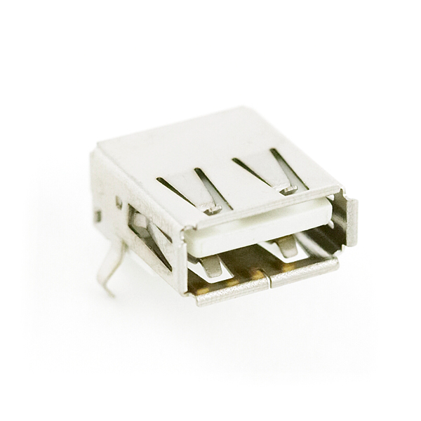
- USB Female Type A SMD Connector

USB Female Type A SMD Connector Product Help and Resources
Core Skill: Soldering
This skill defines how difficult the soldering is on a particular product. It might be a couple simple solder joints, or require special reflow tools.
Skill Level: Competent - You will encounter surface mount components and basic SMD soldering techniques are required.
See all skill levels
Comments
Looking for answers to technical questions?
We welcome your comments and suggestions below. However, if you are looking for solutions to technical questions please see our Technical Assistance page.
Customer Reviews
5 out of 5
Based on 1 ratings:
Well used parts fail.
Not out of poor design but simply due to high use. It is a good idea to have a spare in the bin when one fails.
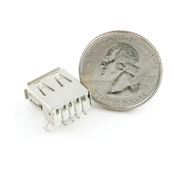
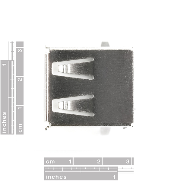
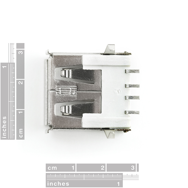
The scale overlays in the images are VERY WRONG! This component is NOT nearly 30mm long as it is shown. It is 14.4mm long according to the datasheet. The length in the datasheet is comparable to the Molex 48258-0002 and the Lumberg 2410_06. Also consider that a quarter is 24mm in diameter and look at the photo with a quarter in it.
Please stock a through hole version!
Where's the PCB thru hole version?
I think the scale images are wrong... 1" square?
FYI, I'm using this part on a PCB I'm making for school. Haven't made the board yet, but judging from the gerber files, the footprint in the Eagle library doesn't really match. If you look at the part, the two feet on the outside are power and ground and are spaced slightly further away from the two differentials on the inside. I presume so you can run wider traces to them to handle 500mA.
So...don't trust the footprint in the Sparkfun Eagle Library, because after laying the actual part on top of a 1:1 print out of the gerber file, the feet don't quite line up.
I agree with this. The footprint seems wrong. Even on the UBW32 which it says should work. The parts that go through the hole (not the pads or connectors) line up, but on the UBW32, the unregulated power connector prevents the pin from going all the way in the hole and catching. The USB on the other side of the hole seems fine.
The spacing on the pads is wrong, but possibly doable. The UBW32 pads are too close together, especially since on the USB part, the pin spacing between 1-2 and 3-4 is greater than 2-3. Has nobody at sparkfun actually tried this?
I'm planning on using this, so I cooked up a component in Eagle CAD. Maybe someone else will find it useful: https://s3.amazonaws.com/LFL-Site/sparkfun-usb-a.lbr
edit: I used the datasheet to create the footprint, so it will hopefully work better than the one in the sparkfun library. The pads are 1.0mm wide instead of 0.9, for a little wiggle room and because they were that much (indicates a tiny distance between forefinger and thumb) easier to place.
FYI, the attached datasheet shows a recommended footprint from the bottom view. This is opposite from pretty much every datasheet I've ever seen. Just a heads up so you don't switch pins 1 with 4 and 2 with 3 which would cross your data lines and power/ground. The front view is correct though.