- Home
- Product Categories
- Monochrome
- Basic 16x2 Character LCD - Amber on Black 3.3V

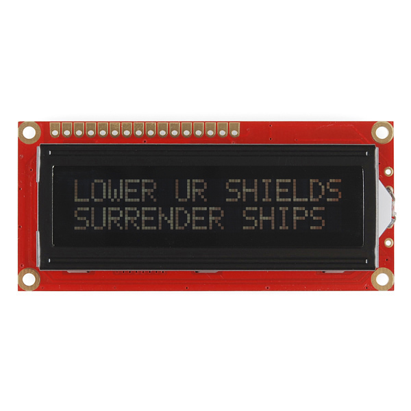
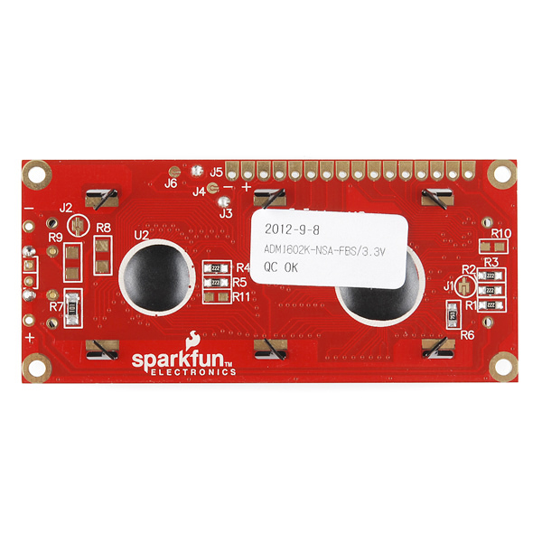
Basic 16x2 Character LCD - Amber on Black 3.3V
This is a 16 character by 2 line display that runs at 3.3V. Utilizes the common ST7066/HD44780 parallel interface (datasheet). Interface code is widely available for many different controllers and systems. You will need ~11 general I/O pins to interface to this LCD screen. Includes amber LED backlight.
- High quality STN 16x2 character LCD
- 3.3V power supply
- Amber LED Backlight
- 5x8 dot characters
- ST7066 controller
- 1/16 duty cycle
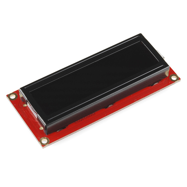
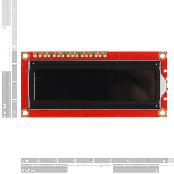
- 0.34 x 1.4 x 3.2" (8.6 x 36 x 80mm)
Basic 16x2 Character LCD - Amber on Black 3.3V Product Help and Resources
Basic Character LCD Hookup Guide
May 28, 2019
Liquid crystal displays (LCDs) are a great way to output a string of words or sensor data to a display for visual feedback. In this tutorial, we'll learn about LCDs, how to print a string of words to a 16x2 basic character LCD and create custom characters.
Core Skill: Soldering
This skill defines how difficult the soldering is on a particular product. It might be a couple simple solder joints, or require special reflow tools.
Skill Level: Noob - Some basic soldering is required, but it is limited to a just a few pins, basic through-hole soldering, and couple (if any) polarized components. A basic soldering iron is all you should need.
See all skill levels
Core Skill: Programming
If a board needs code or communicates somehow, you're going to need to know how to program or interface with it. The programming skill is all about communication and code.
Skill Level: Rookie - You will need a better fundamental understand of what code is, and how it works. You will be using beginner-level software and development tools like Arduino. You will be dealing directly with code, but numerous examples and libraries are available. Sensors or shields will communicate with serial or TTL.
See all skill levels
Core Skill: Electrical Prototyping
If it requires power, you need to know how much, what all the pins do, and how to hook it up. You may need to reference datasheets, schematics, and know the ins and outs of electronics.
Skill Level: Competent - You will be required to reference a datasheet or schematic to know how to use a component. Your knowledge of a datasheet will only require basic features like power requirements, pinouts, or communications type. Also, you may need a power supply that?s greater than 12V or more than 1A worth of current.
See all skill levels
Comments
Looking for answers to technical questions?
We welcome your comments and suggestions below. However, if you are looking for solutions to technical questions please see our Technical Assistance page.
Customer Reviews
4 out of 5
Based on 1 ratings:
Good little screen
These displays really come in handy on portable sensor projects. I used the tutorial with the Sparkfun Inventor's Kit for Arduino to figure out the wiring.
If you want less wiring, you can now get I2C backpacks for these.
I eagerly await the day when there is a flat, flexible display screen that can be sewn into clothing.
You can also use it on 4-bit mode , this way you only need 6 Output pins to use it (if you're reading back data from the LCD's controller,you'll need 7 I/O pins)
I got this display today as replacement for my HD44780 . its a pin replacement of 5v HD44780 and indeed it worked perfect BUT it works only on 5v and not 3.3v . this is supposed to be a 3.3v display so what I have to do to make it work on 3.3v ?
I powered mine with 3.3V but used 5V for the logic and it still works great: http://computersandcircuits.com/temp_center#.VBuAlPldUaA
Would this work with Arduino FIO?
Why don't you have green on black
Here's the final say on this LCD to clear up any confusion.
1. It runs on 3.3V supply voltage
2. It is 5v logic, so no level converter is needed
3. There is already a 100 Ohm resistor on the board for the LED backlight. No extra resistor is needed.
Hook it up like you would any normal 5V LCD, except use 3.3V for the supply.
I have been trying to make it work with arduino uno but all I get is "_ _ _ _ _ _ _ _ ". I have been using 5v. Could that be the cause of the failure? Or my LCD is fried?
5v supply or 5v logic? The way I hooked mine up was with 3.3V supply voltage but just ran 5v logic straight from the Arduino. Here's what I built with it: http://computersandcircuits.com/temp_center#.VBuAlPldUaA
Does anyone else find this voltage combination a bit... fishy?
I can understand designing a board that can run off of both 3.3V and 5V logic, where the supply voltage range is 3.0 to 7.0V and the I/O can accept the same range.
I don't know, for some reason I keep thinking that if your I/O voltages are higher than your supply voltage you'll end up with a current backflow through the supply pins.
It is strange but I set it up with a 3.3V supply and just used straight 5V logic and it's been working perfectly for several years now. http://computersandcircuits.com/temp_center#.VBuAlPldUaA
Has anyone found out if this is really a 3.3V LCD or a 5V? I need this color for a project but I need to know whether it's 3.3V or 5V for the board I'm designing for it!
Should be 3.3V for the LCD panel (noted in the product part and the typical electrical characteristics), with 1.9V for the backlight (probably a little LED, hence the note in there stating that for 16mA across the LED with a 3.3V power supply, you should use a 100Ohm resistor to burn off the excess voltage)
The confusion seems to stem from the 7.0V figure in the absolute maximum ratings section, which is measured between Vss and Vdd. I may be mistaken, but I think that's the maximum voltage before you definitely fry the LCD. The other maximum values, e.g. the 3.5V for power, inputs, I think are "don't go over this, it's not what it's designed for, and we're not sure it'll do what we say it's supposed to do if you go over anyway".
So, stick to the 3.3V. If in doubt, get this part before you design your PCB (always a good idea, to verify pinouts and pin spacing!) - or if you absolutely must, design it so that you can drive it using either 3.3V or 5V.
I designed my board to be able to run 3.3v or 5v to the LCD. What I'm wondering is are the I/O pins 3v as well or 5v? Will I need a level converter to hook to the 5v arduino pins?
Ok so I've got this hooked up and working right now. It runs off of 3V supply for LCD power but uses 5V logic. Have tried it with my Arduino and my ChipKIT UNO with success. Put a resistor inline with the LED to drop the voltage. I've got a 220 in there (all I had in front of me) and the backlight is dim, but it's there. It needs a 100ohm as the datasheet states. This will bring the 3.3V down to 1.9V @16mA for the LED.
Update! This LCD has a 100 Ohm SMD resistor already in the system. Just apply 3.3v to it and you're fine :D
Can I hook up the data bus directly to my Arduino UNO, or do I need a level converter? The data sheet for the LCD contradicts itself. This is sold as a 3.3V LCD but Data sheet says up to 7V MAX can be it's SUPPLY power. Input voltage is stated to be VSS - VDD (which is I believe the power input level). Then on the very next page on the absolute maximum rating it says 3.5V max on inputs..?
How to enable backlight ??? pin 15 and 16 ??? how to connect backlight with arduino??
Thanks.
Has anyone had a problem with contrast/backlighting? Everytime I change the display message, the contrast changes and I need to re-adjust the trimpot.
Nope...
Maybe not enough current supply?
(The 5v pin on my Arduino works just fine, maybe try something like that to confirm it isn't defective.)
I may have missed it, but I cant seem to find anywhere what the driving voltage for the LED backlight is. Pins 15 and 16, labeled LED+ and LED-. Is it also 3.3 volts?
Will I still be able to use this with the standard Arduino LCDLibrary?
What about http://www.arduino.cc/playground/Code/LCD3wires, if I use a different chip (3.3v compatible)?
Yes it works with the the standard Arduino LIbrary. I just completed the below example. The only thing I changed was the example did not connect the backlight, and I did (to verify it works).
http://arduino.cc/en/Tutorial/LiquidCrystal
Are both ST7066-0A or ST7066-0B available? If not, which model is?
Amber on Black or Black on Amber?
Is it something like this:
http://www.flickr.com/photos/27565375@N04/2938007065/
Amber on Black.
woo - replying to old posts ftw!
Anyway, see if there's a little polarizing film on there. If there is, just flip it over. Voila - black on amber. Should work for any LCD (but not really recommended for color ones)
I have successfully had this working at both 3.3V and 5V logic. The only difference I can see is the response time seems marginally slower at 3.3V and the contrast pot had to be wound a long way to see the screen at 3.3V. I'm driving it with a PIC by the way.