- Home
- Product Categories
- Monochrome
- SparkFun Serial Enabled 16x2 LCD - Red on Black 3.3V

SparkFun Serial Enabled 16x2 LCD - Red on Black 3.3V
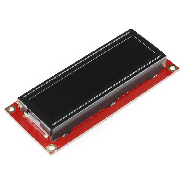
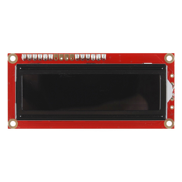
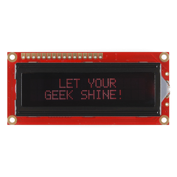
The serial enabled LCD allows you to control a parallel based LCD over a single-wire serial interface. Included in this product is a red on black 16x2 LCD connected to our serial backpack. The backpack, based around a PIC16LF88, takes a TTL serial input and prints the characters it receives onto the LCD. The installed firmware allows for a number of special commands so you can clear the screen, adjust the backlight brightness, turn the display on/off, and more.
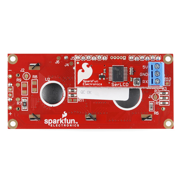
Communication with SerLCD requires 3.3V TTL serial at a default baud rate of 9600bps (8-N-1). You can adjust the baud to any standard rate between 2400 and 38400bps. The power, ground and RX pins are all broken out to a 3.5mm pitch screw terminal.
SerLCD has the ability to dim the backlight to conserve power if needed. There is also a potentiometer on the backpack to adjust the contrast.
Note: Though the silkscreen may say '5V', this is a 3.3v Serial LCD. Connect to a 3.3v power source.
- PIC 16LF88 utilizes onboard UART for greater communication accuracy
- Greater processing speed at 10MHz
- Incoming buffer stores up to 80 characters
- Backlight transistor can handle up to 1A
- Pulse width modulation of backlight allows direct control of backlight brightness and current consumption
- All surface mount design allows a backpack that is half the size of the original
- Faster boot-up time
- Boot-up display can be turned on/off via firmware
- 1.425x3.15" - 1" Thick
SparkFun Serial Enabled 16x2 LCD - Red on Black 3.3V Product Help and Resources
PIC-Based Serial Enabled Character LCD Hookup Guide
May 29, 2018
The PIC-based serial enabled character LCD backpack is a simple and cost effective solution for interfacing to character Liquid Crystal Displays (LCDs) based on the HD44780 controller. The backpack simplifies the number of wires needed and allows your project to display all kinds of text and numbers.
Hackers in Residence - The ElectricBone
June 25, 2014
Drum machines and keyboards have been the standard for making digital music, but how do you make electronic music if you're trained to play the trombone? One of our Hackers in Residence, Carlos Mello, took it upon himself to find a solution to that very question.
Core Skill: DIY
Whether it's for assembling a kit, hacking an enclosure, or creating your own parts; the DIY skill is all about knowing how to use tools and the techniques associated with them.
Skill Level: Noob - Basic assembly is required. You may need to provide your own basic tools like a screwdriver, hammer or scissors. Power tools or custom parts are not required. Instructions will be included and easy to follow. Sewing may be required, but only with included patterns.
See all skill levels
Core Skill: Programming
If a board needs code or communicates somehow, you're going to need to know how to program or interface with it. The programming skill is all about communication and code.
Skill Level: Rookie - You will need a better fundamental understand of what code is, and how it works. You will be using beginner-level software and development tools like Arduino. You will be dealing directly with code, but numerous examples and libraries are available. Sensors or shields will communicate with serial or TTL.
See all skill levels
Core Skill: Electrical Prototyping
If it requires power, you need to know how much, what all the pins do, and how to hook it up. You may need to reference datasheets, schematics, and know the ins and outs of electronics.
Skill Level: Competent - You will be required to reference a datasheet or schematic to know how to use a component. Your knowledge of a datasheet will only require basic features like power requirements, pinouts, or communications type. Also, you may need a power supply that?s greater than 12V or more than 1A worth of current.
See all skill levels
Comments
Looking for answers to technical questions?
We welcome your comments and suggestions below. However, if you are looking for solutions to technical questions please see our Technical Assistance page.
Customer Reviews
No reviews yet.
I need a Fritzing Parts file for this part.
Are any problems can occur if I connect it to UNO 3.3V and something else is also connected to the 5V?
Hi Could this display be used as a drop in replacement for the serial enabled 7segment disply, part 11441
Thx
Br
Carl
Has anyone successfully gotten this running at 38400 baud? The data sheet says it supports it but when I set the baud rate and try to print text to the screen I get "close" gibberish.
I'm using the following code: void setup() { pinMode(8, OUTPUT); delay(200);
The "hello, world" comes out looking close but with some letters being replaced with special characters ("w" replaced with a pi symbol) or "o" being replaced with it's umlaut equivalent: "ö".
Anyone have any insight?
In the v2 code, the sleep() function is disabled. Is there a reason? I'd like to remain in low-power mode most of the time (running off batteries) and the 3mA or so current drains the batteries when not actively used.
Edit: Ignore everything I said here earlier. I figured it out.
I was trying to modify the Analog Read Serial code from Arduino.cc to print it to my LCD. I modified the code to look something like this:
/* AnalogReadSerial Reads an analog input on pin 0, prints the result to the serial monitor
This example code is in the public domain. */
void setup() { Serial.begin(9600); }
void loop() { int sensorValue = analogRead(A0); selectLineOne(); Serial.print(sensorValue); } void selectLineOne(){ //puts the cursor at line 0 char 0. Serial.write(0xFE); //command flag Serial.write(128); //position delay(10); } Now, the values are off, i.e. when the potentiometer is turned all the way to where it should be zero, it says something like 37. However, the 1023 is constant. I can fix this problem by making the Serial.print(sensorValue); a println statement, but then there will be the two vertical bars at the end. Can someone help me fix this problem? Thanks so much for the support! -Boj
Also, is it possible to do strikethrough in the comments? The formatting help doesn't help me with that, but I think I've seen someone do something like that.
This screen works pretty well. It's maybe not the brightest backlight, even full on, but the contrast adjustment makes the letters crisp and readable. The serial interface is very straightforward. It even operates at 3.0V without much difference (a little dimmer than 3.3V, but not much).
I have ported LiquidCrystal library for use with the serial LCD you can look at my code here. Still working on finishing all the documentation. But putting up for now hopefully someone will find it usefull.
http://arduino.cc/playground/Code/SerLCD
-Thanks
Hi, I used to buy old serial enabled screen and this time, I have bought this serial enabled screen (LCD-09068).
My problem is when I start my sketch with an old serial enabled screen, all works fine. When I start my sketch whith this new screen, all the thing I print on the screen are behind bigs red blocks. It's like if all the pixels of the screen were on, and behind, I can see the things I print...
Is it a normal thing?
To control the contrast you have to turn the screw-like piece on the back (near of the Rx screw). I think no external potentiometer is need. Hope this can help!!
To get rid of the big red blocks,you need to connect a Potentiometer to control the contrast(I used 10K from Radio Shack). That should enable you to see the writing on the LCD. The datasheet says it comes with a 10K pot (screw like) on the back, but I'm not sure how you can vary that. It seems kinda fixed. I ended up connecting the screw to the external pot and when I vary the external pot, the red blocks disappear and the text appears clearly in red on a black background. Some help in the data sheet as to how the vary the supposedly 10k Pot on the back would be helpful. Has anyone else found a better way to control contrast without an external pot?
Are these backpacks soldered on?
Yes they are. I was hopping they were just plugged into an header.
About Serial Enabled 16x2 LCD - Red on Black 3.3V
sku: LCD-09068
It says "Note: This is a 3.3v Serial LCD. Connect to a 3.3v power source."
But, when I opened the package, it says 5V on the
little serial board terminal. (as shown on in the above pic).
The main LCD pcb has a 3.3V label on it.
My guess is, that little serial board will work with either 3.3 or 5V, but my LCD is only good for 3.3V..
Am I right?
Note: Though the silkscreen may say '5V', this is a 3.3v Serial LCD. Connect to a 3.3v power source.