- Home
- Product Categories
- 7-Segment
- 7-Segment Display - LED (Blue)

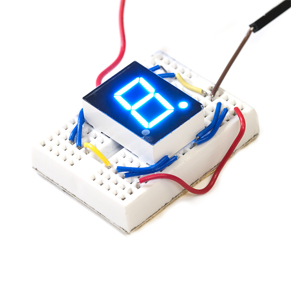
7-Segment Display - LED (Blue)
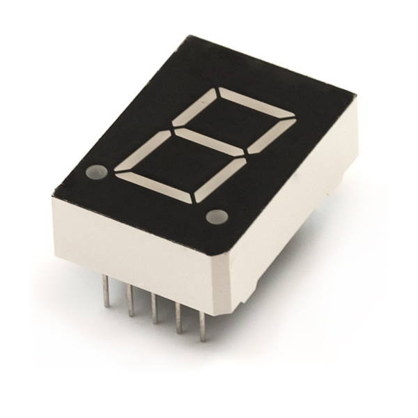
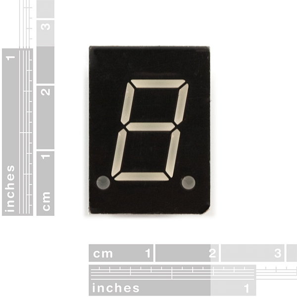
Your basic 7-segment LED, but in blue! Common anode. Two decimal points, but only the one on the right is wired. Digit height is 0.6". Overall height is 1".
Check out this tutorial on how to use this product with the 74HC595 Shift Register and Arduino. Thanks Patrick and Mycha!
- Datasheet
- Arduino Library (Thanks Derek!)
7-Segment Display - LED (Blue) Product Help and Resources
Core Skill: Electrical Prototyping
If it requires power, you need to know how much, what all the pins do, and how to hook it up. You may need to reference datasheets, schematics, and know the ins and outs of electronics.
Skill Level: Competent - You will be required to reference a datasheet or schematic to know how to use a component. Your knowledge of a datasheet will only require basic features like power requirements, pinouts, or communications type. Also, you may need a power supply that?s greater than 12V or more than 1A worth of current.
See all skill levels
Comments
Looking for answers to technical questions?
We welcome your comments and suggestions below. However, if you are looking for solutions to technical questions please see our Technical Assistance page.
Customer Reviews
4.5 out of 5
Based on 2 ratings:
Works great
Took me some trial and error but I figured out the pins without using a shift register
Pinout seems correct
You say the pinout on the datasheet is wrong, but the (current) datasheet shows the same pinout as you do...
I think we may have updated the data sheet and forgotten to remove the note in the product description here, but I'll double check. Thanks for the review!
I can't figure out from the datasheet whether I need to put a resistor between each pin and GND to avoid damaging the LEDs.
The Sparkfun tutorial has pictures which don't appear to have any resistors. Are there resistors built in to the package?
old comment is old, but I'd better leave an on-topic comment to make up for the banter down below ;)
There are no resistors built-in on the package. That would be a poor component design choice as that would make assumptions about the circuit it would be included in. You'll have to supply your own resistors. There are circumstances where you might not need them, but it's generally recommended that you do have them. You can get independent resistor arrays to make assembly easier, or just use separate resistors. You only need resistors for the segments (8 if including the decimal point).
UPDATE : Finally got around to creating a video. Hope it helps. http://youtu.be/9B5Kr3gMvZ4
If you are new to seven segment displays and you are using an Arduino Uno with a shift register. Here are a few things I learned while using this product.
DECIMAL POINTS : 1 on the bottom right is available
CONNECTIONS TOP L-R : [ 10 / Q6 / G ] , [ 9 / Q5 / F ] , [ 8 / Power ] , [ 7 / Q0 / A ] , [ 6 / Q1 / B ]
CONNECTIONS BOTTOM L-R : [ 1 / Q4 / E ] , [ 2 / Q3 / D ] , [ 3 / Power ] , [ 4 / Q2 / C ] , [ 5 / Q7 / DecimalPoint ]
SHIFT OUT CHALLENGES : If you are reading the tutorials in the Arduino Workshop book by John Boxall you may experience some confusion when sending values to this display. The author specifies using a common CATHODE segment display. From what I understand this product is the opposite i.e. common ANODE. As a result, the matrix the author shares with you will not work. The numbers will be garbled on the display. Apparently after much research I realized that the solution is to reverse every value. In other words, to make the display work you will need to send a 0 rather than a 1 to turn on the led segment. Totally confusing until I figured this out. Also, the only way I could get my Arduino sketch to work was to add a "B" at the beginning of the value. So for example, the book states that if you want to display the number "0" on your segment you should send the following value "11111100" or the value"252." However, with this product you would actually need to send the following value "B00000011." Note the "B" at the beginning. I dont have the decimal conversion for this value you will need to research that on your own.
FAULTY PRODUCTS : I am not sure what you will experience when ordering this but I found that out of the three units I ordered only one functioned properly. One unit the G segment didn't work. The second unit the G segment was barely visible. The Third unit worked properly. Consider ordering more than one to make sure you finish your project.
Hope this helps you. Took me hours to figure this out.
Thanks for mentioning the Arduino Workshop book. I'm here looking for all the parts for it but couldn't find a common Cathode seg display. Glad to see this will still work.
I've made a short tutorial on how to make a push button countdown timer using one of these, its at http://www.jacob-unwin.com/making-a-7-segment-display-countdown-clock/
Jacob your example was excellent, especially compared to Quinns where the numbering is inconsistent with the pins and segments. Great work, for some bizarre reason Segment G, the middle bar, isn't appearing in "2" or "3" but appears in the other numbers off the 2 pin. The code you provided seems consistent so this error is odd.
why not connmon cathode so I can use my 4511 driver ??
without using shift register
//setup pins for 7 segment
const int SegA = 2; const int SegB = 3; const int SegC = 4; const int SegD = 5; const int SegE = 6; const int SegF = 7; const int SegG = 8; const int SegH = 9; //DP
void setup() { pinMode(SegA, OUTPUT); pinMode(SegB, OUTPUT); pinMode(SegC, OUTPUT); pinMode(SegD, OUTPUT); pinMode(SegE, OUTPUT); pinMode(SegF, OUTPUT); pinMode(SegG, OUTPUT); pinMode(SegH, OUTPUT); }
void loop() {
//blanking out the leds digitalWrite(SegA, HIGH); digitalWrite(SegB, HIGH); digitalWrite(SegC, HIGH); digitalWrite(SegD, HIGH); digitalWrite(SegE, HIGH); digitalWrite(SegF, HIGH); digitalWrite(SegG, HIGH); digitalWrite(SegH, HIGH);
delay(500);
//led A active //this is to allow you to write down the active led to create numbers digitalWrite(SegA, LOW); digitalWrite(SegB, HIGH); digitalWrite(SegC, HIGH); digitalWrite(SegD, HIGH); digitalWrite(SegE, HIGH); digitalWrite(SegF, HIGH); digitalWrite(SegG, HIGH); digitalWrite(SegH, HIGH);
delay(500);
//led B active digitalWrite(SegA, HIGH); digitalWrite(SegB, LOW); digitalWrite(SegC, HIGH); digitalWrite(SegD, HIGH); digitalWrite(SegE, HIGH); digitalWrite(SegF, HIGH); digitalWrite(SegG, HIGH); digitalWrite(SegH, HIGH);
delay(500);
//led C active digitalWrite(SegA, HIGH); digitalWrite(SegB, HIGH); digitalWrite(SegC, LOW); digitalWrite(SegD, HIGH); digitalWrite(SegE, HIGH); digitalWrite(SegF, HIGH); digitalWrite(SegG, HIGH); digitalWrite(SegH, HIGH);
delay(500);
//led D active digitalWrite(SegA, HIGH); digitalWrite(SegB, HIGH); digitalWrite(SegC, HIGH); digitalWrite(SegD, LOW); digitalWrite(SegE, HIGH); digitalWrite(SegF, HIGH); digitalWrite(SegG, HIGH); digitalWrite(SegH, HIGH);
delay(500);
//led E active digitalWrite(SegA, HIGH); digitalWrite(SegB, HIGH); digitalWrite(SegC, HIGH); digitalWrite(SegD, HIGH); digitalWrite(SegE, LOW); digitalWrite(SegF, HIGH); digitalWrite(SegG, HIGH); digitalWrite(SegH, HIGH);
delay(500);
//led F active digitalWrite(SegA, HIGH); digitalWrite(SegB, HIGH); digitalWrite(SegC, HIGH); digitalWrite(SegD, HIGH); digitalWrite(SegE, HIGH); digitalWrite(SegF, LOW); digitalWrite(SegG, HIGH); digitalWrite(SegH, HIGH);
delay(500);
//led G active digitalWrite(SegA, HIGH); digitalWrite(SegB, HIGH); digitalWrite(SegC, HIGH); digitalWrite(SegD, HIGH); digitalWrite(SegE, HIGH); digitalWrite(SegF, HIGH); digitalWrite(SegG, LOW); digitalWrite(SegH, HIGH);
delay(500);
//led H active digitalWrite(SegA, HIGH); digitalWrite(SegB, HIGH); digitalWrite(SegC, HIGH); digitalWrite(SegD, HIGH); digitalWrite(SegE, HIGH); digitalWrite(SegF, HIGH); digitalWrite(SegG, HIGH); digitalWrite(SegH, LOW);
delay(500);
}
code for not using shift register... be sure to put resisters on the common cathodes and wire each pin to the corresponding segment pins on the back of the display. I can provide more information once I get home today.
//setup pins for 7 segment
const int SegA = 2; const int SegB = 3; const int SegC = 4; const int SegD = 5; const int SegE = 6; const int SegF = 7; const int SegG = 8; const int SegH = 9; //DP
void setup() { pinMode(SegA, OUTPUT); pinMode(SegB, OUTPUT); pinMode(SegC, OUTPUT); pinMode(SegD, OUTPUT); pinMode(SegE, OUTPUT); pinMode(SegF, OUTPUT); pinMode(SegG, OUTPUT); pinMode(SegH, OUTPUT); }
void loop() {
//blanking out the leds digitalWrite(SegA, HIGH); digitalWrite(SegB, HIGH); digitalWrite(SegC, HIGH); digitalWrite(SegD, HIGH); digitalWrite(SegE, HIGH); digitalWrite(SegF, HIGH); digitalWrite(SegG, HIGH); digitalWrite(SegH, HIGH);
delay(500);
//led A active //this is to allow you to write down the active led to create numbers digitalWrite(SegA, LOW); digitalWrite(SegB, HIGH); digitalWrite(SegC, HIGH); digitalWrite(SegD, HIGH); digitalWrite(SegE, HIGH); digitalWrite(SegF, HIGH); digitalWrite(SegG, HIGH); digitalWrite(SegH, HIGH);
delay(500);
//led B active digitalWrite(SegA, HIGH); digitalWrite(SegB, LOW); digitalWrite(SegC, HIGH); digitalWrite(SegD, HIGH); digitalWrite(SegE, HIGH); digitalWrite(SegF, HIGH); digitalWrite(SegG, HIGH); digitalWrite(SegH, HIGH);
delay(500);
//led C active digitalWrite(SegA, HIGH); digitalWrite(SegB, HIGH); digitalWrite(SegC, LOW); digitalWrite(SegD, HIGH); digitalWrite(SegE, HIGH); digitalWrite(SegF, HIGH); digitalWrite(SegG, HIGH); digitalWrite(SegH, HIGH);
delay(500);
//led D active digitalWrite(SegA, HIGH); digitalWrite(SegB, HIGH); digitalWrite(SegC, HIGH); digitalWrite(SegD, LOW); digitalWrite(SegE, HIGH); digitalWrite(SegF, HIGH); digitalWrite(SegG, HIGH); digitalWrite(SegH, HIGH);
delay(500);
//led E active digitalWrite(SegA, HIGH); digitalWrite(SegB, HIGH); digitalWrite(SegC, HIGH); digitalWrite(SegD, HIGH); digitalWrite(SegE, LOW); digitalWrite(SegF, HIGH); digitalWrite(SegG, HIGH); digitalWrite(SegH, HIGH);
delay(500);
//led F active digitalWrite(SegA, HIGH); digitalWrite(SegB, HIGH); digitalWrite(SegC, HIGH); digitalWrite(SegD, HIGH); digitalWrite(SegE, HIGH); digitalWrite(SegF, LOW); digitalWrite(SegG, HIGH); digitalWrite(SegH, HIGH);
delay(500);
//led G active digitalWrite(SegA, HIGH); digitalWrite(SegB, HIGH); digitalWrite(SegC, HIGH); digitalWrite(SegD, HIGH); digitalWrite(SegE, HIGH); digitalWrite(SegF, HIGH); digitalWrite(SegG, LOW); digitalWrite(SegH, HIGH);
delay(500);
//led H active digitalWrite(SegA, HIGH); digitalWrite(SegB, HIGH); digitalWrite(SegC, HIGH); digitalWrite(SegD, HIGH); digitalWrite(SegE, HIGH); digitalWrite(SegF, HIGH); digitalWrite(SegG, HIGH); digitalWrite(SegH, LOW);
delay(500);
}
It's sad that the digit isn't symmetrical. I'm making a digital clock out of four of these and missed that the center segment is closer to the top of the digit. I was going to flip the 3rd digit over so that the two decimal points would form a colon. :/
Can this be used outside without the display fading due to the sun?
Sorry for the noob question, but I'm trying to figure out how to use this in a schematic in Eagle. Anyone have any ideas?
The device you'd want to add is SparkFun-Displays.lbr:7-SEGMENT-DISPLAY-1"-RED . That's the 7-Segment Display - LED (Red), which has the same pinout and physical dimensions.
Why does the comments go in a descending order? Shouldn't the most recent comments be first??
now that you say that I'm wondering that too
We're really hoping the "best" comments get more stars so they rise to the top and are useful to more people.
As for C/RC, as Kamiquasi said it's a touchy subject :) I'm just sayin', most of us here at SFEHQ use vi.
One gotcha with the ranking is that it is per-level. E.g. I just gave you an extra star, which put your comment above mine at this level. But being replies to comments that are at 1 star means they don't actually rise to the top of the entire comment thread. Perhaps they should?
That can get complicated fast :\ Does a 20 star reply to a parent with 2 stars rank its parent higher than a top-level comment with 10 stars?
We're taking the reddit approach here (without downvotes, of course) and it seems to be working out alright. We love hearing different ideas, though!
To answer your question - yes. That's based on the assumption that the 'upvote' is for the content of the comment 'as is', and not for its context (e.g. ancestors). If you have two comments at 10 stars, then its hierarchical level would probably prevail, although it gets a bit arbitrary. Others may prefer to see just the comments with the highest stars and add a header/footer to expand the associated hierarchy, though.
Yep, complexity. But complexity is an excellent motivator for adding toggles to user preferences ;)
On the other hand, support tickets are an excellent deterrent :D
Resolved; wontfix
;)
Chronological vs Reverse Chronological is a debate that may spiral into such epic discussions as vi vs emacs ;)
Just to confuse matters further, though, there's an additional sort on ranking (the little star + number bit) for each tier of comments. So if there's a comment that you believe deserves extra attention, 'upvote' it (and its ancestors).
I'm using this 7-segment display with the 74HC595 and found that the pin-out for unit that I received matches neither the one in the datasheet nor the one provided above. I'm guessing it's up to each individual to determine the pin-out for each individual unit. Other than that, everything works great!
Bought one of these and a 74HC595 Shift Register. I'm pretty new to electronics, and I'm still confused on how this thing is properly grounded, doesn't require resistors, etc but it works. I used the bildr tutorial on the 74HC595 and the Arduino tutorial to get it running. I think I learned more about shift registers just by wiring this up than any other reading I could have done.
The display itself is incredibly bright, almost blindingly. It is the rich, bright blue as shown in the product photos. It is not cyan, which makes it look that much better. Tempted to pick up the 4x unit with SPI now, just because they look so darn good.
Figured it out
The color is not really blue, it is closer to cyan. It is certainly does not have the appearance of 465nm as listed in the data sheet.
The color does not match Sparkfun's blue bar graph display even though the datasheet's are from the same manufacturer and have the same specs. The bar graph has a violet tint to it and side by side the colors are not even close.
There is a thin plastic protective covering over the display which I am fairly certain is supposed to be temporary. I am not completely certain since it was stuck on there really well. I had to pull so hard to get it off I lost a segment in the process, presumably due to mechanical damage on one of the pins.
I have the segment LED and shift register connected as shown in the tutorial (linked above in the product description) and can get all of the lights to light up at any given time. I am having difficulty getting the correct lights to light up as I send commands to the shift register. I upload the same code to the Arduino time and time again, but different combinations of LEDs are lighting up. Any thoughts or insight on my dilemma?
Looking carefully at the photos you'll see that the display is not symmetrical above and below the center segment. The data sheet does not accurately represent the actual part. I like the breadboard-friendly top and bottom pin row arrangement.
Found the correct pinout on the comment to the red version of this part. Sparkfun - you should correct the datasheet.
Any idea how to wire this thing ? I bought two but cannot get any LED to light up. The data sheet indicates pin 5 and 10 (!) to be +ve. I assumed that grounding any other pin via 200 ohm should light up a segment. There is marking for pin 1 but how are the others designated ? What stupid thing am I doing ?