- Home
- Product Categories
- Magneto
- Hall-Effect Sensor - US1881 (Latching)

Hall-Effect Sensor - US1881 (Latching)
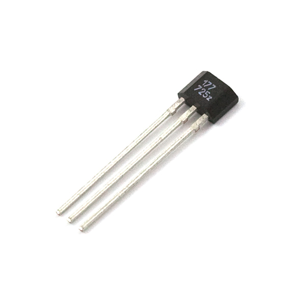
The US1881 is an integrated Hall-Effect latched sensor. That's nice but what does it do? Holding a magnet near the sensor will cause the output pin to toggle. This makes for a robust presence sensor. A reed sensor also works nicely, but can be limited by the glass encapsulation and size. A Hall-Effect sensor is much smaller, but can handle less current than a reed switch.
The device includes an on-chip Hall voltage generator for magnetic sensing, a comparator that amplifies the Hall voltage, and a Schmitt trigger to provide switching hysteresis for noise rejection, and open-collector output. An internal bandgap regulator is used to provide temperature compensated supply voltage for internal circuits and allows a wide operating supply range.
If a magnetic flux density larger than threshold Bop, DO is turned on (low). The output state is held until a magnetic flux density reversal falls below Brp causing DO to be turned off (high).
- 3.5V to 24V DC operation voltage
- Low current consumption
- Temperature compensation
- Wide operating voltage range
- Open-Collector pre-driver
- 50mA maximum sinking output current
- Reverse polarity protection
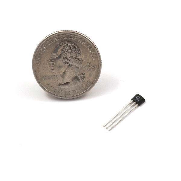
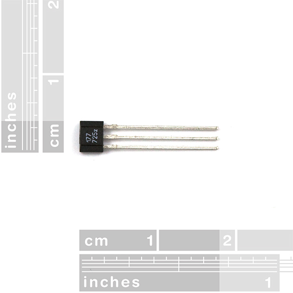
- Lead Free Package: TO-92
Hall-Effect Sensor - US1881 (Latching) Product Help and Resources
1 of 1 found this helpful:
Linear, Latching, or Basic Hall Effect Sensor?
This is a latching hall effect sensor. The sensor will turn ON when a magnetic field from a magnet is applied. The sensor will turn OFF when the reverse field is applied.
Core Skill: Programming
If a board needs code or communicates somehow, you're going to need to know how to program or interface with it. The programming skill is all about communication and code.
Skill Level: Rookie - You will need a better fundamental understand of what code is, and how it works. You will be using beginner-level software and development tools like Arduino. You will be dealing directly with code, but numerous examples and libraries are available. Sensors or shields will communicate with serial or TTL.
See all skill levels
Core Skill: Electrical Prototyping
If it requires power, you need to know how much, what all the pins do, and how to hook it up. You may need to reference datasheets, schematics, and know the ins and outs of electronics.
Skill Level: Noob - You don't need to reference a datasheet, but you will need to know basic power requirements.
See all skill levels
Comments
Looking for answers to technical questions?
We welcome your comments and suggestions below. However, if you are looking for solutions to technical questions please see our Technical Assistance page.
Customer Reviews
No reviews yet.
What is the required range magnet must be to trip sensor? Would using a stronger magnet have any effect on this?
Hi there, it sounds like you are looking for technical assistance. Please use the link in the banner above, to get started with posting a topic in our forums. Our technical support team will do their best to assist you.
Otherwise, it looks like the magnetic specifications are listed on page 4 of the datasheet. You can also find a link to the datasheet under the Documents tab beneath the product pricing.
The problem with this is that it's latching. I bought a bunch of AH1815-P-B's from Digikey which work a lot better in many cases since they are non-latching.
https://www.digikey.com/product-detail/en/diodes-incorporated/AH1815-P-B/AH1815-P-BDI-ND/5453089
The only drawback is that the output needs a pull-up resistor, but that too can be useful since it's possible to have multiple sensors share an output. Of course the Arduino can just be configured to have a pullup on the input.
any plans for sparkfun to carry non latching hall effect sensors? I'd rather not pay shipping to two different retailers.
plz??????? :)
here is a picture of a cat to convince you.
(http://images.paraorkut.com/img/funnypics/images/l/lol_cat-12926.jpg)
I third this request.
Forth
Fifth! I am going to other vendors when I buy items for this project because your not carrying a non-latched sensor. I like you guys but need to buy from someone that has it.
Yes, this hall effects sensor latches on/off depending on the polarity introduced to it. I needed it to latch on/off when a magnetic field was/was not present, which this is not set up to do by design. But I found a simple way around that...
I am using the sensor with an Arduino, so my implementation may not work for your setup. Instead of providing constant power (5v) to pin 1, I instead connect it to a digital pin that I have set as an output. Pin 2 goes to ground and pin 3 is read as a digital input. Note: As mentioned in other comments, I use a 10k pull-up resistor between power (digital out to pin 1) and output (digital in from pin 3) to get a clear on/off state.
In the loop code, I first set the hall sensor power pin to HIGH and delay for as short as 10ms, read the latched state from it (on/off), and then set the hall sensor power pin to LOW and delay another 10ms.
Cycling the power resets the state of the sensor so you can poll its output to see if the magnetic field (of the polarity that latches it ON) is still present or not. The delays are necessary to give it time to reset, otherwise it will give unexpected results.
This allowed me to make a simple open/closed presence sensor without having to do something funky with the magnet to get it to flip poles each time. I hope this helps!
I tried doing this, but found that even with the 10k pull-up resistor, I got a ton of noise in the signal. The only way I've been able to reliably use this is to use two magnets near to eachother, one to turn the latch on and one off.
Nice post. I used your hardware setup and did the same thing. Works great. I tried to use smaller delays but I too arrived at 10ms as a good interval to allow the sensor to reset.
I just used this technique as well. It's perfect. It may be a good idea to put this up as a link in the documents section for the part.
thank you for this bit of advice
Feed it with 3.3v on the VCC. That makes it not latch. How about that as a solution :)
Doesn't work for me.. I've even tried 1 second and it won't work. Any ideas?
Relevant code: int interval=10, delayer=1000, timer; [...] if (millis() > timer + interval) { // reset digitalWrite(SWITCH_PIN, LOW); delay(delayer); timer = millis(); digitalWrite(SWITCH_PIN, HIGH); } where SWITCH_PIN goes to the VDD leg. I bring one side of the magnet close, it goes to 1, I pull it away and wait, it usually doesn't drop to 0. Code is naïve on purpose.
I am also looking for a non-latching sensor.
Spark fun clearly don't give a dam but I was able to find some more information with this latest datasheet.
You've got 3 pins from the front (the triangle edge). Left to right, power, ground, output.
Stick a 10k pull up between 5v and output. Then it'll latch on/off depending on the poll you use.
hope that helps
it did!
I would like to second the need for a non-latching sensor.
any plans for sparkfun to carry non latching hall effect sensors? I'd rather not pay shipping to two different retailers.
Pay attention to the pin out on the data sheet ;) There are two sensors (surface mount and through-hole) with different pin designations.
This. I had it correct in my prototype, but misread the sheet for the production install. What a pain. You want the second column for through hole (UA Pin No).
Yes, the ATS177 is a latching sensor that requires a reverse field to turn it off.
I would like to see the Allegro A1301EUA-T Hall Effect Sensor. It is a continuous-time, ratiometric, linear Hall-effect sensor optimized to accurately provide a voltage output that is proportional to an applied magnetic field. It has a quiescent output voltage that is 50% of the supply voltage and provides 2.5 mV/G.
Non-latching and omnipolar would be a nice option, too; I opted for a Honeywell SS451A, which I tested successfully with the Arduino. (Ratiometric would be cool, but not necessary for what I have in mind, so I went for simple.)
Mark- I got the same part (Honeywell SS451A). I had a bit of trouble figuring out the pinout, and did a few things differently from you. (I made my sensor count edges, and I didn't use a resistor) Here is my basic writeup (inc wiring information and code).
that's useful, thx for posting. do you know of equiv parts available at jameco? they have 30 varieties but none appear to be omnipolar. their parametric search sucks so hard to be sure.
Yeah, some analog sensor to measure the distance to a magnet would be very handy!
PLS ADD IT WITH LAST COMMENT..IN FOOT PRESSURE MEASUREMENT PROJECT I need to measure the PLANTAR pressure of the foot.SO I NEED CIRCUITS PLS HELP
You may want to look at our force sensors instead for your application. This sensor is designed to work with magnetic fields, not pressure.
http://www.melexis.com/Assets/Hall_Applications_Guide__3715.aspx
so this is the first breakthru I've had.
For convenience, Melexis: Hall Applications Guide.
Has anyone got a schematic and possibly some pictures for this sensor. I'm trying out the schematic in the Datasheet but the Arduino isn't having any of it :(
can anyone tell me if this sensor will be able to detect a EMP over a distance of 2 meters( the EMP device has been proven to work to 7 meters)
I've seen a couple of interesting sensors manufactured by Allegro Microsystems, the A1318 and A1319. Both are ratiometric linear hall effect sensors, which outputs a very nice voltage signal proportional to the magnetic flux it senses. They're designed for rather strong magnetic fields, and would complement the Sparkfun's portfolio for magnetic sensors.
Just a hint!
I've tried to feed it 3.3v with internal pull-up from Arduino Uno. What happens is that it doesn't latch but works brilliant for detecting the magnetic field. Crazy and great!
One great attribute of latching sensors is in direction sensing in repetitive applications. Suppose there are two magnets in proximity with different polarities facing out. Passing a latching sensor in one direction produces a positive going pulse (on quickly followed by off), while passing the sensor in the other direction produces a negative pulse (last cycle's on not off until next cycle).
Ok, so I'm a bit confused on the operation of these, what I'd like to use it for would be an on/off switch for LED throwies. The description and all the other comments say this is a "latching" sensor, my understanding is that if the switch is off, and I bring a magnet near it, it will turn on, but even when I take the magnet away it will stay on, until I bring the magnet back again which will turn it off. So does it just alternate between on and off whenever it gets triggered or am I missing somthing?
i have these wired with 5v on 1, signal on 2 (middle), and gnd on 3
it senses the magnet but the output pin is showing .5 volts I was expecting 5v or at least 3 volts.
i had the same results with 3 different units. I also tried a 10k resistor across 1 and 3 which didnt help.
Update::::
nevermind, had the wrong pinout. 2 is gnd, 3 is signal. working now
sure would be nice if the basic pinout was shipped with the product.
i am making a chess board that will automatically record moves (and eventually store in pgn format) Will this type switch work for that application. I would mount the switch (64 of them, 8 x 8) under the board then, using magnetic chess pieces, the switch would activate when a piece is moved.
I need something small and low cost. that can fit in the size of a chess square and work through a small piece of wood or cardboard. a $5 switch would make for an expensive project. this looks like it would do the trick if it will work through the chess board. I need to get chess pieces with strong magnets.
per the other users, non-latching would be better for my project.
I have a project where I want need to index the location of the rotation of a small 5vdc and use the sensor basiclly as a limit switch. I am working in a very some space so a traditional limit swich is not possible or practical. Anyway the Hall Effect Sensor would have to be very close proximity to the stepper motor, so will this interfer with the readings from the sensor?
I am looking at building an RPM sensor for a CNC spindle (aka a Dremmel). Would this be usable given the high speeds it has - 10K-20K)?
Hi all, i read all your comments. i hope u have already worked with hall effect sensor.I have started working for a project FOOT PRESSURE MEASUREMENT USING HALL EFFECT SENSOR.. I purchased hall 310 H64. but it does not work..currently i am in need of circuits ans suggest me which type of hall effect sensor to purchase and where?
Hey guys, I got one of these sensors and am trying to build a tachometer (motor speed meter) using this device.
So when i connect my hall sensor (5v,gnd, 10k pullup at the output), if i move a small magnet close to it (1/2 inch) it indeed switches the signal as expected, (i check the signal level on an oscilloscope)
But if i put my hall sensor next to a small dc motor (parallel to the shaft) (such as this: http://www.solarbotics.com/product/tpm2/ , or even this : http://www.robotmarketplace.com/products/0-PL1596.html)
I expect to see more or less a square wave pattern on the oscilloscope, but i dont. My motor spins like crazy (~10,000 rpm) but no effect on the hall sensor. Any ideas ?
thanks in advance A.
I'm confused by how you set up your sensor. If you set it up so that alternate polarities rotate past a single side of the sensor it should work fine. Usually in tachometers, I would guess non latching types are used because a single fixed magnet can turn the sensor on as it passes and again with each successive pass rather than just once on the first. Earlier someone suggested resetting the sensor by switching the power and then delaying, which is clever for some uses, but would not work for a tachometer higher than 100 rpm, or faster than the minim reset time. Also for anyone else reading, don't think about buying this for a levitator because it can't be done, or maybe I just can't figure out how to. An electromagnet would switch this on or off, and a floating magnet with reverse polarity approaching the reverse side of the sensor would cause no change. I should have thought about that before I purchased this
When this sensor is powered on, what state is it in?
here is explanation on how hall effect sensor works
http://sensors-actuators-info.blogspot.com/2009/08/hall-effect-sensor.html
This should werk fine for RPM detection and Speed Detection. This is the same device used in automobiles for anything that rotates and is the Base for the ignition system.
Sparkfun--
Can we please have a linear analog or non-latching digital hall sensor? The Bildr tutorial you list references both types of hall effect sensors as well as yours sold here. An analog sensor may be easier to use as the problem of dealing with open-collector outputs (as seen here) will be gone; only a voltage must be fed into an ADC.
Thanks! baum
p.s. in fact there are very cheap ($.85) non-latching sensors on mouser...
When I ordered these for my rain gauge project, I missed the word "latched" in the description! Perhaps SparkFun could change the part name to "Latched Hall Effect Sensor"?
Fortunately, I also ordered 2 reed switches that should work for my project. I'll have to find something else to do with these, or use the method suggested by JPFlash for resetting the latch by controlling the power with a Digital Output. I thought that was a clever idea.
Heres the circuit i use to interface this chip to a pic microcontroller: Connect the Hall effect sensor to Ground (middle pin) and power (left pin from triangle side). Then connect the hall effect output (right pin) to both power (Vdd should about 5 volts) through a 10k resister (R1) and to the noninverting input of a 741 op amp. Next connect the inverting input of the op amp to to ground through a 100 ohm resistor (R2) and to the op amp's output through a 10k resistor (R3).
This circuit should amplify the voltage by a factor of 11 (see wikipedia non-inverting amplifier for more detail).
Testing showed the circuit output at 4-5V when the hall effect sensor was latched on and under 2V when latched off. -John Fitz
To add to this suggestion... Rather than multiplying the output voltage, I've gotten better results feeding it into an op amp comparator, like this:
http://en.wikipedia.org/wiki/Operational_amplifier_applications#Comparator
V1 comes from the pulled-up Hall sensor output, and V2 comes from a voltage divider set to give 250 mV. The output will go to one rail or the other depending on the sensor's output.
This setup has a couple of advantages. First, it goes all the way to GND and VCC. Second, if you have more than one Hall sensor, it will require only one voltage divider (one op amp per input with the voltage divider's output going to each one).
EDIT: change R2 form 100 ohm to 1k ohm
I had a heck of a time getting these to work reliably for me with an arduino. I tried all kinds of code tweaks and wirings and eventually gave up and went for the much simpler reed switch (which I didn't know existed at first) and now my project works great!
http://www.youtube.com/watch?v=kAReep0QhpU
Nice work! For some things a reed switch is just plain easier and simpler to use. Each has its own application.
Hi all..
I am new to this forum.
I brought above Hall Effect Sensor from sparkfun & built circuit as per datasheet above, ie "Typical Three-Wire Application Circuit".
I am using normal fridge magnets. Against my expectations, to get 0 & 5V ouput at pin 3 of sensor, I observe only 0 & 0.5V output(Supply voltage +5V DC).
Is it due to normal fridge magnets?
How do I get 0-5V output?
Thanks everybody,
myetrx
^^ He's actually right about the datasheet. I just tried using that on mine and it FINALLY WORKED!
Anyone having any luck with the Arduino and this sensor?
This sounds like one of those hall effect sensors that requires a field reversal to turn off - in other words, a south pole latches it high, north pole returns it to low.