- Home
- Product Categories
- Buttons and Switches
- SparkFun Blackberry Trackballer Breakout

SparkFun Blackberry Trackballer Breakout
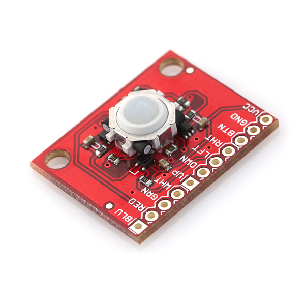
This is a breakout board for our Blackberry Trackball. The four spindles on the trackball have a tiny circular magnet the end; each of these are paired with an SMD hall effect sensor, which are used to measure up, down, left and right movements of the trackball. An SMD momentary switch is placed under the trackball to give you a select switch. The BTN line will be pulled low when the switch is pressed.
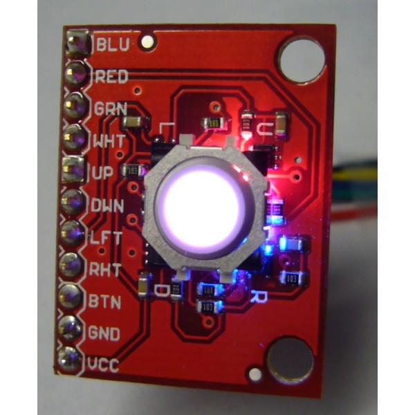
Also included on the Trackballer are 4 LEDs: red, blue, green and white. These can be powered to light the clear trackball up any color you can imagine.
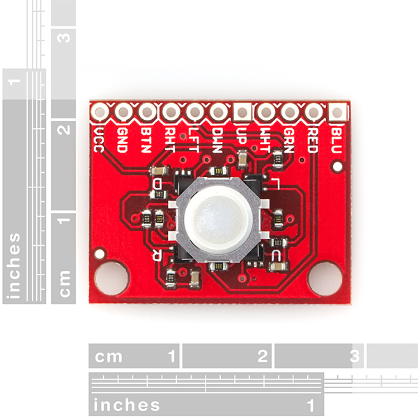
All features are broken out to a 0.1" pitch header. Regulated, 2.5-5.25VDC power must be provided to power the Hall sensors. The trackball is attached with strong CA glue. Board comes as shown, with all components populated.
The hall-effect sensors and trackball combo are surprisingly sensitive. A slight roll of the trackball creates multiple high/low transitions on the four axis pins, easily picked up by any microcontroller essentially giving you the option of adding a mouse to your project. A 360° rotation of the trackball, along a single axis, will result in about 9 high/low transitions.
- Center select button
- 360° direction
- Hall effect sensors measure up/down/left/right movements of trackball
- Red, blue, green, white LEDs to light up the trackball
- All pins broken out to 0.1" pitch header
- 1.1x0.85"
SparkFun Blackberry Trackballer Breakout Product Help and Resources
Core Skill: Soldering
This skill defines how difficult the soldering is on a particular product. It might be a couple simple solder joints, or require special reflow tools.
Skill Level: Noob - Some basic soldering is required, but it is limited to a just a few pins, basic through-hole soldering, and couple (if any) polarized components. A basic soldering iron is all you should need.
See all skill levels
Core Skill: Electrical Prototyping
If it requires power, you need to know how much, what all the pins do, and how to hook it up. You may need to reference datasheets, schematics, and know the ins and outs of electronics.
Skill Level: Competent - You will be required to reference a datasheet or schematic to know how to use a component. Your knowledge of a datasheet will only require basic features like power requirements, pinouts, or communications type. Also, you may need a power supply that?s greater than 12V or more than 1A worth of current.
See all skill levels
Comments
Looking for answers to technical questions?
We welcome your comments and suggestions below. However, if you are looking for solutions to technical questions please see our Technical Assistance page.
Customer Reviews
No reviews yet.
ddegn: I just received a trackballer and I agree the green LED seems much weaker than the others. This is strange since green LEDs usually apear brighter than other colors because our eyes are more sensitive to that wavelength of light. I also agree this is still a way cool product.
My green LED is also extremely dim. I'm putting 1K on the other LEDs to balance it up. Yes this is a very cool product. Hopefully SF will fix the LED issue in the next patch.
BTW I did check the resistor - 180R same as the others.
The LED voltage drop is 2.1V
I'm testing with 5V into the LED inputs.
Pearce: That's exactly the switch that is underneath the trackball.
No it is not. The footprint of the COM-08720 is much bigger than the footprint seen in the Eagle PCB Layout program.
You need to use a tactile button such as the following:
EVQ-PQMB55
http://search.digikey.com/scripts/DkSearch/dksus.dll?Detail&name=P8091SCT-ND
Ah, You're right, I could have sworn we used the other switch
Question, what's the resolution? In a shaft encoder it would be steps per revolution. Not clear how you'd represent that for a trackball. But do you get fine control like a mouse? Does the slightest nudge show up as a step, or is it chunky? Thanks!
Hi Mike - it's about 9 to 10 transitions per 360 ball rotation.
Good question. I wish I could figure out a way to quantize it. The trackball is very sensitive. A very slight roll of the track ball equate to many blips coming out of the appropriate hall sensor. Perhaps we could mark the ball with a sharpie and count the blips... Not scientific, but I'll try to get it done and report.
what is required in order to use this on a Raspberry pi project?
This trackball can be made extremely sensitive. The best approach for increasing the sensitivity on this device would be to use analog pins rather than digital ones. The hall effect sensors will sweep out a Sine wave between 0 and ~3.3v depending on input voltage. Sampling the analog input would yield you a better range. – 0.3 to (VCC + 0.3) the output of the hall effect sensor. You would get some portion of the resolution of your dac (8bits is the resolution of most DAC's on common micro controllers on arduinos and such) but you must multiply that by 4 as there are 2 poles to the magnet an rotating 180 degrees causes 4 iterations of the wave. Then you must multiply by 9 because there are 9 rotations per 360 degrees that would give you 256 bits of resolution per 360 degrees.
Looking at the provided hall effect sensor datasheet, there is a schmidt trigger controlling a cmos output. I don't think that you are going to get a sine wave from this.
Using this breakout board from the BeagleBone Black: http://www.linux.com/learn/tutorials/765810-beaglebone-black-how-to-get-interrupts-through-linux-gpio
Using two ripple counters and a pin mux chip to give the trackball an I2C interface (handy for arduino) http://monkeyiq.blogspot.com.au/2014/01/ripple-counting-trackballer-hall-effects.html
Probably a batter IC combo to do the later. Hints welcome ;)
Anyone has the arduino code for it and wiring diagram.
Hi guys I think I have a problem with this product. I'm trying to simply read with arduino the state of the directional pin ,but whenever I move the ball in any direction,the state of the related pin freezes on HIGH and won't change unless I roll the ball that direction some more times. For example : A0 connected to UP pin -> I roll the ball toward the UP direction -> analogRead(A0) constantly giving me 1023 (HIGH) even if I'm not touching it anymore ; if I roll the ball toward UP again,it suddenly stops giving signals. Is it normal? Is it related to sensors? It does it with all the direction btw. Thanks in advance.
That sounds like the sensor itself may be malfunctioning. Contact techsupport@sparkfun.com and they'll be able to help you further.
why not using a RGB LED instead of separate R, G, B, and white LEDs?
I think it's a practical issue. Although I can't tell for sure (we have one, but it's pretty well-enclosed now), I think there isn't any space to put a component underneath the trackball itself - it would have to be seated up higher somehow, complicating manufacture and making it more prone to damage. That leaves you with 4 corners where you can put something. RGB+W seems like a reasonable thing to decide on at that point - the Bold 9000 only had a single white LED, also placed in a corner. With current LED manufacturing they could probably have used 4x RGB '0603' (more like 0606) LEDs, but those sure are tiny :)
Could I use this as a mouse for my raspberry pi?
I'm making a wrist mounted Pi, and I'd rather have a trackball than a touchscreen.
Thanks!
You'd have to hook it up to something like an Arduino Leonardo... Now I really need one of these!
I'm going to be working on that exact thing once mine arrives! I'll post an update letting you know how it's going. :)
So how's the project going?
More info on the Hall Effect sensor and the momentary button used for the trackball: http://www.semicon.panasonic.co.jp/en/products/analog/hallic/#05
Anyone else having issues with the trackball mounting? mine came off after two days of use...
Sorry to hear you ran into that issue! Contact us at techsupport at sparkfun dot com and include your order number and we will get you taken care of.
I kind of hate that it's not clear if I must buy this board AND the trackball, or just the board. Could you please clarify this?
This comes with the trackball attached to the pcb, along with the LEDs. You can purchase the trackball by itself here, but this breakout board has the ball included.
The trackball on mine also broke off, however I didn't have any trouble epoxying it back on. When I put it back on I put extra epoxy around the edges of the trackball and now it is solid as a rock. Other than that this works great, its very smooth, and reads very easily.
Does anyone have any info on how noisy the outputs are? I am interested in using it for a digital design class project, and was wondering how much (if any) debouncing would be required to get a decently clean signal out.
Watch out. The trackball assembly is just glued on in 2 tiny spots and cannot take much horizontal force before popping off. Be careful not to apply too much pressure.
did anyone used it with arduino? can you provide me with the code? THANKS
Same Here.Can anyone provide the code.
Rampagesmr: Pearce: That's exactly the switch that is underneath the trackball.
No it is not. The footprint of the COM-08720 is much bigger than the footprint seen in the Eagle PCB Layout program.
You need to use a tactile button such as the following:
EVQ-PQMB55
http://search.digikey.com/scripts/DkSearch/dksus.dll?Detail&;name=P8091SCT-ND
Can anyone confirm that this switch fits properly under the center?
Thanks!
Hi,
I need to know which p/n must be used for the central smd switch under the ball.
Thank you.
Since you don't sell the hall effect sensors, is it possible to use Allegro A3214ELHLT-T or A3213ELHLT-T? Or are there any other sensors better suited which can be found on Farnell?
According to the schematic there are pull-up resistors on the hall effect sensor outputs... But according to the datasheets for the sensors themselves, these resistors are not needed - it appears to drive its output high or low, rather than just pulling it low or letting it float... right?
How is this RoHS compliant, but the trackball without the breakout board isn't?
My fault. The initial order of trackballs could not be verified if they were RoHS or not. The most recent shipments are RoHS compliant. I've changed the status on the trackball.
Sorry if this sounds noob, but could anyone tell me how to best implement this without using interrupts on a AVR. I'm just learning and I got it to work using interrupts but I only have two external interrupt pins.
Thanks
-Cyrus
If you can't use interrupts then you will need to poll the I/O lines for the four directions on a near-constant basis. You could probably get away with infrequent polling until you detect a pulse, and then poll more frequently to detect all the state transitions until the activity dies down again...
Alternately - you could solve the problem in hardware by hooking all four sensors up to an XOR gate, and hooking the output of that to your interrupt pin. A state change on that interrupt pin would then tell you it's time to poll the four Hall Effect sensor I/O pins again to see what actually changed.
I am on the forums, you can message me if you need more help.
But, this requires 4 I/O pins plus 1 interrupt. How can you figure out which pin's value has been changed? When polling the values for all 4 pins, it is too late to get those pins previous values.
save the previous value to a variable, then read the new state and compare, works like a charm for me on a PIC:
For below, my ball is connected to PortA pins 0-3 (button on 4)
Port A --> Pressed (variable)
If(pressed AND 16 = 0){
//button pressed
}
If(pressed AND 8 up){
//up has changed
up = (pressed AND 8)
}
If(pressed AND 4 down){
//down has changed
down = (pressed AND 4)
}
If(pressed AND 2 left){
//left has changed
left = (pressed AND 2)
}
If(pressed AND 1 right){
//right has changed
right = (pressed AND 1)
}
My trackball played up after not all that much use. I was using glues and stuff so my fingers weren't always clean but not too bad either.
The ball didn't work well in the "up" direction.
I applied some contact cleaner and roll the ball around a bit. This fix the problem but the button stopped working at some point after that.
After a few days I applied more cleaner and push down on the ball while rolling it around. The button began to work again.
Does anyone know of a project that uses one of these as a trackball for a computer? This would be perfect for integrating into a car's gear shift knob to control an in car pc.
@TRInc - <br />
Check out the VUSB firmware for avr microcontrollers. It's a software based solution to emulate USB signals, and you could use it to emulate a USB mouse.<br />
<br />
http://www.obdev.at/products/vusb/index.html
Is this just the breakout board, or are the components already soldered on? I was unsure after reading through the description.
Thanks!
I'm looking at making a custom trackball mouse for my computer, could i simply take a store bought mouse and solder this in it instead?(plan on making a custom enclosure), i have almost no electronics knowledge beyond soldering so im looking for a way to use existing products and just sort of cut and paste in things i want.
Hi, can somebody please tell me what switch is under the blackberry trackball? Is it the same COM-08720 switch being sold in Sparkfun?
Thanks !
That's exactly the switch that is underneath the trackball.
thanks for your prompt answer !! :)
Lovely product, capable of picking up quite subtle trackball movements despite the apparent low resolution in the spec. Certainly I have to move my finger as delicately as I can to trigger it only once.
The green LED is very weak, much more so than the other two colours, making full colour mixing tricky. This is a tiny complaint compared to the overall niceness of the trackballer breakout.
I just received a trackballer and I agree the green LED seems much weaker than the others. This is strange since green LEDs usually apear brighter than other colors because our eyes are more sensitive to that wavelength of light. I also agree this is still a way cool product.
My green LED appears as bright as the others, but maybe that is just me?
At 9 pulses for 360 degrees that only gives about 40 degrees resolution per pulse - not very precise. I suppose this is good for menu navigation and scrolling where the resolution doesn't need to be so fine.
Got it today!!!
its so amazing!
Its a little bigger than the size of a quarter!
Can we get part numbers or datasheets for the LEDS?
wow, I looked at my BB and sure enough, that's how it works. I've had it for 2 years and never realized that's how it works. I would have called it cheesy engineering if I had never used it. quite effective at a low cost.
a perfect product to replace odometer in small size rolling robots !
I'm waiting for my end of month money :)
How did this work out? I'm thinking not so well, if you ever used one of these they can get gunked up with just a little dirt or dust. Many a time did I have to pull mine out and soak it in isopropyl and blow it out with air.
Potato chip salt was the worst.
What a great idea! We'll have to give that some thought and try it out.
Can this work with Arduino?
I want to make it change from Green to Blue when i move the ball downwards. Is there a sample code via a hyperlink, or can you guys explain how you coded it?
Thank you so much!
ZK
i wrote a little sketch (arduino-0017) that fades the leds as you scroll up and down. see it at:
http://tinyurl.com/sfeTrackballCode
works much better with the blue and red leds though... the green one is kind of weaksauce.
The code works fine but it uses 2 interrupts. I am using Arduino pro mini which has only 2 interrupts. How can I get 4 directions and one button work? Thanks.
of course. numeric electronic it's like a lego game, you juste have to plug component between each others, take care of max current for port, pin and gates, and it roll. next step program your stuff, it can work with arduino pic and many component.
Maybe somebody will give you some sample program...
Seems like it would be nice to have 4 mounting points for this board rather then just 2. Guess you just gotta be gentle?
How much anchoring do ya need? The headers in a breadboard are enough for most of my tinkering. The standoff holes also help for mounting in enclosures and on walls. Every wall needs a trackball.
"How much anchoring do ya need?"
well if this were to go on the bottom of a robot. 3 or 4 mounting holes would eliminate the risk of large bending moments. if a robot with this hits something, the trackball board will likely snag, and possibly snap.
Nice idea... directional sensor?
I plan to mount it to a piece of aluminum, which has a pocket cut out of the rear (so it will mount flush on the front). The way the holes are, it is difficult (but not impossible) to specify the pocket dimensions. I would like to see either a) the holes lined up with the trackball, or b) the components which currently reside in the space between the holes moved, so that the board can be screwed to the flat metal surface.
Alternatively, placing the holes on an area of extra board with no copper (extending the board material by .250" on each end) would work, too.
Not a criticism- I like it and plan to buy more.
Forgot to add, the traces for the red and blue LEDs are pretty close to the hole, which necessitates insulating hardware.
I like the board, but it would be cool if it was a little easier to mount.
it has 4 outputs because the trackball functions as a D-pad. in each direction is a small hall-effect sensor(magnetic switch) to signal if the trackball is pointing in a direction. example: if the trackball is pointing toward left the left hall sensor signals that its on.
This will be lots of fun. Just wondering why there are 4 directional outputs, when its a 2axis component. Is is possible to treat it like a quadrature encoder and get higher resolution?
You got it figured out. It's a sneaky way of engineering. The blackberry folks designed the ball so that only one of the four spindles spins when pushing the ball. It's sneaky but works without the user noticing anything.
nvm, it looks like the track ball only engages the magnet in the direction the trackball is turning? in the video the magnet moves to the side a bit before it starts to spin.