- Home
- Product Categories
- Kits
- SparkFun MegaShield Kit

SparkFun MegaShield Kit
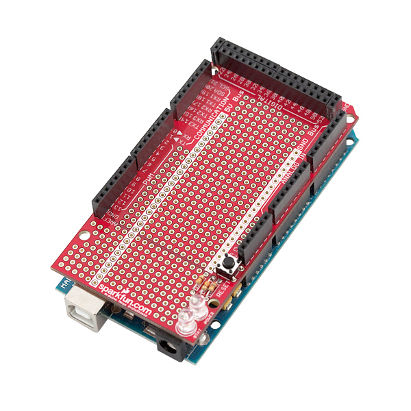
The Arduino Mega now has its very own prototyping shield! The SparkFun MegaShield mates with the Arduino Mega board and gives the user a prototyping area, two general LEDs, and, most important of all, the Arduino Mega reset switch is brought to the top level. The shield also works with our small breadboards if you don't want to solder to the prototyping area.
This comes in kit form and must be soldered together by the end user. Please note - we do not ship assembly instructions! All soldering is through-hole (relatively easy) but always check your component orientation before soldering!
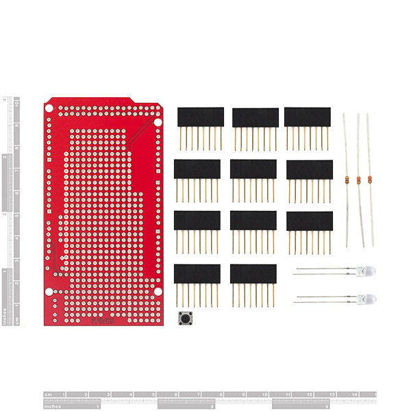
- 1x MegaShield PCB
- 11x 8-pin Arduino Stackable Header
- 1x Bright 5mm Green LED
- 1x Bright 5mm Red LED
- 2x 330 Ohm resistors
- 1x Momentary push button
- 1x 10k resistor
- All Arduino Mega pins are brought to the top level
- 5V and GND power busses
- Power and stat (connected to D13) LEDs
- Reset Button brought to top level
- Protoshield Schematic
- Eagle Files
- Assembly Tutorial by Bob Gallup
- Arduino Home Page
- GitHub
SparkFun MegaShield Kit Product Help and Resources
Core Skill: Soldering
This skill defines how difficult the soldering is on a particular product. It might be a couple simple solder joints, or require special reflow tools.
Skill Level: Rookie - The number of pins increases, and you will have to determine polarity of components and some of the components might be a bit trickier or close together. You might need solder wick or flux.
See all skill levels
Core Skill: Electrical Prototyping
If it requires power, you need to know how much, what all the pins do, and how to hook it up. You may need to reference datasheets, schematics, and know the ins and outs of electronics.
Skill Level: Rookie - You may be required to know a bit more about the component, such as orientation, or how to hook it up, in addition to power requirements. You will need to understand polarized components.
See all skill levels
Comments
Looking for answers to technical questions?
We welcome your comments and suggestions below. However, if you are looking for solutions to technical questions please see our Technical Assistance page.
Customer Reviews
2 out of 5
Based on 5 ratings:
4 of 4 found this helpful:
not great
potential risk of shorting over usb jack and no pads to connect to arduino header pins...not sure what the point is without that...
Thanks for the feedback. I'll pass this along to our Engineers for consideration if this item comes up for revision.
3 of 3 found this helpful:
A little short of being a good proto shield
-Includes a green and red LED, but doesn't label which is which and they are super-bright... a bit overkill for status lights. -5 v bus runs right over the USB connector, creating a shorting hazard. With proto board seated fully, this section of the board can't be used anyway as it is touching the USB connector. -Kit includes only 8 pin headers. One must be cut to length for the 6 pin spot (yet a 6 pin header is available in the Uno kit) and the other extra must be cannibalized to make two 2-pin connectors to cap off the large block on the end of the board. Not hard if you have good small side-cutters, but I cringe to think of using anything larger. -No breakouts for the headers; either need to make connections through the top or solder on the bottom. This would be nice for at least the main headers along the side, but who knows... maybe that would cost too much space.
Overall it works, but there are pitfalls.
4 of 4 found this helpful:
Fit poorly together and in Arduino
The headers didn't fit into the PCB until the sides were sanded down. Once that was done, the shield would get stuck in the Arduino and took a lot of careful pulling to release it. I had planned on using this to quickly attach and detach the circuit from the Arduino, so this product was completely unusable.
2 of 2 found this helpful:
Be careful with the Eagle files....
I appreciate Sparkfun releasing the Eagle files as an Open Source resource. However, it appears that the names of the pads are in some cases reversed. This is very confusing. The symbolic names of the pads are in the opposite order than the silk screen. Since nothing is wired to these on this board, it doesn't matter, but if you are using this as base for designing your own PCB, it is very confusing.
The board is valuable but as another reviewer pointed out, you are going to end up with wires going into the female headers anyway. I am a beginner, but as others have suggested, it might be better to do pure breadboarding and then uses this design as the basis for a shield in the form of a custom PCB.
This is a really stupid shield!
Aside from the issues others have mentioned... having to sand down the headers etc., my big issue was, as the previous reviewer mentioned, this thing doesn't carry the Arduino connections to the board.
Their tutorial shows jumpers connected to the headers, but that's just plain stupid! That's a breadboard, not a proto board. I want the headers to carry through to another shield (a touch sensitive TFT display) once I've wired up the proto board.
I threw the thing in that garbage and ordered the Adafruit proto board instead. That looks like it is what I was looking for in the first place.
I bought one of these and I really hated it. This board was designed to be the top board in the stack. None of the IO pins were brought to the interior of the board, so that you could solder to it. I got one of these http://www.nkcelectronics.com/megashield-kit.html and have been happy ever since.
Wow, you're not joking. This thing is next to useless.
ditto. nkcelectonics breaks out IO, provides a configurable bus (3.3 or 5v), and is overall far better designed.
Hello Mega Users,
I am working on a revision of this shield right now. I'm increasing the annular ring size across the board. I was wondering... would any of you find it useful to have a 3.3V bus? Is the 5V bus useful? I was also wondering if having more buses near the Analog inputs would be useful. Maybe I've been listing to too much of the Who http://www.youtube.com/watch?v=bl9bvuAV-Ao Any feedback would be greatly appreciated. Thanks! - Pete
Pete - Have you made your revision yet?
An ICSP header would be more than welcome. Also, the LEDs are definitely unnecessarily bright. I use the 5V and GND buses so definitely keep those. It might be nice to create extra through-hole connections to the headers - just one extra hole each might be nice.
I completely agree, thats a major flaw.
I think it would be nice to have an ICSP header in the corner across from the leds. I have a similar shield with an ICSP header, but I don't like how it is right in the middle of the shield (brought straight up from the Mega). I also think it would be useful to have a 3.3V bus (possibly split the 5v bus in half).
I love the stuff you guys at Sparkfun do but as other have mentioned, this board needs a bunch of improvements. As far as I can tell the 5v bus is not connected to 5v. All the pins should be brought to a via on the board we can solder too. The space over the USB jack needs to be cut our or not have holes so it does not get used.
Please, made us a new board that is better than the old one.
What good is a prototyping board that doesn't connect the prototyping area to the computer you're connecting to? Are we supposed to run wires from the top of the header connectors into the prototyping area? Note to SparkFun - this board is no fun.
WARNING: v1.3 of the eagle files have a connection error. J9 is incorrectly wired in library part. Highlighting, D22 in schematic shows D52 on the board. D24->D50, D26-D48, etc. Won't hurt the prototypers but using this lib part on your boards will make coasters. Cost me $200. Its just the old 'Gotch ya' of using someone else's part without checking every pin, my fault.
Comes with all 8 pin headers. You'll need 2 six pin headers and 2 2 pin headers. Good luck cutting the eight pin headers - these headers were never meant to be cut. This is really unacceptable.
I don't know about the annular ring size since I just got this kit and haven't soldered it yet. And I haven't used it yet, so can't render an opinion about the power buses.
But here are a few other comments on the kit:
1. LEDs: I don't know that the bright ones are really necessary, nor do they need to be 5mm. The smaller 3mm basic ones, like in the SFE store, would be just fine, I think.
Furthermore, I know it's very minor, but with the clear LEDs, you have to actually plug them in first to figure out which one is green and which is red.
2. Parts list: I think there is an error in the parts list for the connectors on the web page.
Doesn't the shield require 9 of the 8-pin female headers and 1 of the 6-pin female headers? The description says 11 and 1. (My kit was missing the 6-pin, by the way.)
Shouldn't there also be two 2-pin headers included as well, for the two ground and two +5V pins along the edge of the board (at the ends of the digital pins)? The main photo of the shield on the site shows them in place, but they aren't in the parts list (nor were they in my kit).
[cont...]
This shield should have a 6-pin header and 2 2-pin headers. Currently, it only comes with 8-pin headers. The shield will not be fully functional with this arrangement.
Another bummer is that the 6-pin header is at least available but I can not find the 2-pin header to finish building this kit.
You should really fix the schematic because the one header is wrong way around.
Anybody using this be aware that pins from 22 to 52 are actually 52 to 22. Barely noticed it myself.
Woe is me. Why didn't I read other comments and take them to heart. This board is poorly designed, and in my case, my Arduino Mega 2560 R3 won't even function when it's connected.
yeah -- DO NOT BUY THIS SHIELD. it's terrible, and tbh, a bit crappy that you are still selling it after three years of complaints.
the IO pins need to have double holes so you can actually CONNECT TO THEM. seriously, it's such an obvious thing it is hard to imagine it wasn't done in the first pass FOUR YEARS AGO. also, it's way too expensive.
i'm buying Funduinos (MEGA 2560's, $15) and shields for $5 that are far, far better, from China. I really want to support hobbiest-friendly business, and i am willing (and do) pay more for the privilege,l but sheesh, the stuff has to work.
all shields have some frustration or other (they're all compromises) so "only top board" and lack of cutout over USB etc dont bother me much. but the basics need to be present at least.
sorry to gripe but this product is terrible and should be withdrawn.
oh great! the 5V buss touches the metal can of the USB connector. seriously i am actually going to throw out the three i bought (GRRR) and buy one from Adafruit for $2 less, then stock up on some from aliexpress.com (20 day ship time but $5/shield).
it's more work to use these than to buy replacements.
Two comments: * You should make this more like the Arduino protoshield (bring put all I/o pins and have general button and LED footprints) * you should sell the bare pcb after you have done that
None of the IO pins are connected to pads at the interior of the board. This makes soldering it more tedious and improvised than it would need to be. The 5v and GND bus are useful, but they would be more useful if they were positioned differently. Please re-design this board. Also, smaller LEDs would make it more aesthetically pleasing.
Isn't it really abount time these kits can with 2x 10 way header 7x 8 way header 1x 6 way header That way there would be no need to cut up the supplied 11x 8 way headers to make up the board
I used the eagle files of this shield for the base of a PCB shield and please note that there is a mistake. JP5 is correct in the schematic but flipped in the PCB version. You can see that pin one is on the left for JP5 where it should be on the right. This caused me a few hours of frustration so I hope that this helps you out or the schematic is changed!
I wish I read your reply. I was in the same boat as you yesterday. They flipped not just one but three headers 180 degrees, the D14-D21, the D22-D52, and the D23-D53. I was making some changes on my design that I used this design as the basis. Found the mistakes. Please correct them. It's sloppy. I won't trust SPE design as much anymore, plus it took them years to finally add current limiting resistors on their serial 7-segment LED displays. Another thing is the bottom left screw hold is 0.05" off to one side. This works fine on MEGA1280 but in MEGA2560, the screw hole was moved 0.05" to the left and this shield won't line up the screw holes.
According to the Eagle file (and the above pictures), the hole closest to the power jack location is out of position by 0.05" for use with either the Mega or the Due. It should be moved toward the power jack to correct the issue.
Will this shield work with the new Arduino Due?
Be careful, the Due's I/O is 3.3V, and this proto board has a +5V rail running down the middle of it. You will either have to avoid using this rail, or cut-and-jump the trace to the +3.3V pin on JP10.
I'm confused. The MegaShield is extended all the way over the usb connector, apparently to provide a few extra empty holes. But the USB connector is significantly higher than the female headers on the Mega. As it is, if I put the shield on top of the Mega there will be a gap between the shield and the headers on the Mega. This dramatically increases the chance of a wire clipping causing a short or pressure on the board causing something to snap.
This seems like a terrible design decision given that removing 4 rows of blank holes would eliminate this issue. Has anyone tried cutting off the last 4 rows of holes (which would also remove the LEDs, but I assume they are non essential) to allow the board to sit flat?
In addition to the other comments (extremely bright LEDs, board must be top of the stack, etc.) there is another significant problem, the 5V bus trace extends out over the grounded metal USB connector housing (check the image above). If you are not extremely careful you can very easily short the 5V shield trace to ground here. Put a piece of electrical tape on top of the USB connector! I hope sparkfun does a re-design on this one.
This item is a shame, holes are not aligned, there is no big digital connector and you have to build one from small ones
obviously it's almost impossible to get a correct alignment.
I usually got nice product from spakfun, what happened to this item ?
What were you guys thinking, drinking or smoking when you designed this?
You cant use stackable headers with it!
If it was meant to be used with a breadboard you sould have left the whole thing blank!
Sorry, I love your work, but this is crap!
And I bought 2!!!!!
Have a look at the DF Robot version, that's how it should be done!!
Are the connections from the Arduino Mega brought out to PCB holes? In other words, if I need to connect, for example, a digital input to a spot in the protoboard, can I just run a wire from one PCB hole to another or do I have to have a wire coming from the female header?
Also, will I have any issues using this with another shield on top?
Thanks!
Is there any good reason why the header holes centers are not all in the same line ?
Regards
Jorge
It's so that when you are about to solder in the headers, they will stay in place due to friction, which makes it a bit easier.
The LEDs in this kit are WAY too bright! I got blinded by them every time I powered my Arduino on. So I replaced them with some other ones I had. Also, I noticed that the +5volt bus can be touching the metal casing of the USB jack. I am not quite sure if that would cause some damage, but I insulated it with some tape just in case. This works great with a little breadboard for quick prototyping.
why are the led so bright?
I'm guessing that you're supposed to cut two segments off of two of the pieces to make a piece with six segments and two pieces with two segments.
Additionally, the Eagle files will not unzip...
Don't need the ICSP unless reflashing the bootloader. A ten pin JTAG connector would be excellent. For serious debugging, the Aurdino IDE doesn't cut it. ( While your'e at it how about a JTAG ICE MKII clone. My JTAG ICE MKI won't work with the mega1280. The electrical is the same for all other JTAGs; something fishy that JTAG ICE MK1 won't work ).
No on the 3.3. With only 30mA, there is not much that it can be used for except an acel or gyro...unless you add a 500mA 3.3 LDO regulator. I have to use an auxillary 5vto3.3 board for my 3.3v XBEE module. No on the analog bus, but yes on power and ground bus along the PWM, and run them all the way along the "communication" pins too.( in servo pinout of course). Thanks.
Another minor thing to note, and ask about.
There is no through-hole on the board right under the SparkFun logo, nor are there any in the last row where "sparkfun.com" is screened on the top. This means you can not use an 8-pin header in either of the last two rows, which would be handy for an off-board connector.
It seems you could put the holes there and move the logo to the reverse side to make it more useful.
.andy
One last thing about instructions:
Another warning about soldering the LEDs in the correct orientation is probably even more important than the one about the resistors. Resistors are symmetrical, so it doesn't matter which way you insert them, but LEDs are not!
People not familiar with the schematic symbology won't know about which side of the LED illustration on the board represents the cathode and which is the anode, and whether the short or long lead is anode or cathode.
This really should be noted in instructions!
.andy
[...cont]
3. Instructions: I know your product page clearly says that you don't ship assembly instructions, but I think a simple note with some basic pointers in it would be useful. Here are some examples:
- Figure out which is the red LED and solder it on the board in the spot marked POWER. Figure out which is the green LED and solder it in the STAT spot.
- Check the resistors carefully! One is 10K ohm and the other two are 330 ohm. The slots on the board are marked correspondingly. Be sure to match the resistors with the right slot when you solder them on the board.
I wouldn't underestimate the value of very simple instructions or tutorials. They go a long way towards helping people get going with the technology. (I can read a schematic, but I bet not all early users of these tools can.) ladyada, for example, has done an excellent job of making useful instructions.
I DO like your taste in musical inspiration!
Thanks.
.andy