- Home
- Product Categories
- Biometrics
- Carbon Monoxide Sensor - MQ-7

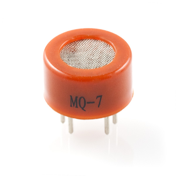
This is a simple-to-use Carbon Monoxide (CO) sensor, suitable for sensing CO concentrations in the air. The MQ-7 can detect CO-gas concentrations anywhere from 10 to 500ppm.
This sensor has a high sensitivity and fast response time. The sensor's output is an analog resistance. The drive circuit is very simple; all you need to do is power the heater coil with 5V, add a load resistance, and connect the output to an ADC.
This sensor comes in a package similar to our MQ-3 alcohol sensor, and can be used with the breakout board below.
Carbon Monoxide Sensor - MQ-7 Product Help and Resources
Hazardous Gas Monitor
June 17, 2016
Build a portable gas monitor to check for dangerous levels of hazardous gases.
Pinouts
Checking with a multimeter and it does not matter if it's A or B on any of the gas sensors that is connected with the breakout board. If you look at the datasheet, it shows that the pins for A1 and A2 or B1 and B2 are internally connected together, respectively. Also the application circuit shows that the polarity does not matter, just as long as the pins on each side align with the breakout board.
Additional Example Tutorial
[Hazardous Gas Monitor w/ Particle Photon](https://learn.sparkfun.com/tutorials/hazardous-gas-monitor0
Calibration
You would need to calibrate the MQ-7 gas sensor and generate an equation that converts the analog values to PPM. To calibrate, you need to use a sample of known concentration in ppm or a CO gas meter. By taking the data points from the known value, this will allow you to create a regression line that is calibrated with the gas sensor. Take a look at the datasheet for more detailed information in regards to calibration.
There are some articles about gas sensors that might be of some use:
Arduino: MQ Gas sensors [ http://playground.arduino.cc/Main/MQGasSensors]
Arduino CO Monitor Using MQ-7 Sensor [ http://www.instructables.com/id/Arduino-CO-Monitor-Using-MQ-7-Sensor/ ]
Air Quality Monitoring [ http://www.howmuchsnow.com/arduino/airquality/ ]*
*Note: The gas sensor in this tutorial is used to sense dust particles.
Core Skill: Soldering
This skill defines how difficult the soldering is on a particular product. It might be a couple simple solder joints, or require special reflow tools.
Skill Level: Noob - Some basic soldering is required, but it is limited to a just a few pins, basic through-hole soldering, and couple (if any) polarized components. A basic soldering iron is all you should need.
See all skill levels
Core Skill: Electrical Prototyping
If it requires power, you need to know how much, what all the pins do, and how to hook it up. You may need to reference datasheets, schematics, and know the ins and outs of electronics.
Skill Level: Competent - You will be required to reference a datasheet or schematic to know how to use a component. Your knowledge of a datasheet will only require basic features like power requirements, pinouts, or communications type. Also, you may need a power supply that?s greater than 12V or more than 1A worth of current.
See all skill levels
Comments
Looking for answers to technical questions?
We welcome your comments and suggestions below. However, if you are looking for solutions to technical questions please see our Technical Assistance page.
Customer Reviews
No reviews yet.
I made a set of experiments using this sensor and wrote an instructable with schematics, code and calibration procedure that can be, with some complications, performed at home: https://www.instructables.com/id/Arduino-CO-Monitor-Using-MQ-7-Sensor/ . Code is relatively complicated since we need to drive transistor with PWM in order to create 1.4V on the sensor - we must use 5V / 1.4V cycles for heating and measuring data. But my results are quite similar to manufacturer's datasheet, so I believe I did it mostly right
Thank you! very interesting project
Kind of frustrating how many places say "just hook it up to 5V", when you can't do that with this sensor. You really don't want the breakout they're selling with this sensor either. If you look at the test conditions in their datasheet, they gave the sensor itself 5V, and had a separate lead for the heater, giving it a 60s@5V, 90s@1.5V while-taking-readings cycle. You'll get lousy results if you "just give it 5V", and you'll get very low voltages if you use the breakout and take readings while only giving it 1.5V. The gas monitor tutorial does a much better job describing that. For my circuit, I have a 5V rail, a separate 1.5V output buck converter, and a relay switching between the two. The sensor itself always gets 5V, the heater on the sensor gets switched between the 5V and 1.5V as specified, I wait 30s into the 90s read cycle to start taking readings then take them every ten seconds from 40 to 80. If you read the datasheet, that's how this is supposed to work.
I've been reading all the ways people have made this MQ7 sensor work, and they seem really complicated. I was wondering if you could provide the details of how you made it work with the buck converter and relay switch. I was going to try member 898076 instructable but I am reluctant to solder the breakout board for the MQ7. Yes, I'm what you call a noob.
i have to sense the carbon monoxide level of vehicle.could this CO sensor sense that concentration .because according to my knowledge,exhaust co concentration of vehicle is about 30,000 ppm ou of new fresh vehicle.so give me solution
We made a cool project with this sensor, which we connected with Arduino Uno to an RGB LED that changes color according to the amount of carbon monoxide in the air. The sensor itself is connected to a helium balloon. You can find the project here >> http://www.instructables.com/id/Red-Balloon/
I'm unclear on how to operate this. I hooked it up to 5V and an Analog pin and am getting readings just fine, but then I'm reading that it's better to cycle the Power using a PWM pin. Can somebody clearly outline a best practice for operating the sensor? Will keeping it on 5V damage the sensor?
Is the accuracy of the meter dependent on atmospheric density? Like really low pressures. Also anybody know a good (and affordable) CO2 sensor?
"Description:...and can be used with the breakout board below." There is no breakout board shown below. Please update the description then delete this comment.
The breakout board is just rendering further in the list of "Recommended Products" - sorry about the confusion on that!
how do you convert the analog read to a pollution value? does anyone have an example with some threshold values? thanks
I brought this sensor about a year ago and I haven't figured out what to do with it, is a complex piece of hardware, the procedure to calibrate and adjust this device are just ridiculous complex, you would require to generate fixed and measurable amounts of C0 in a test chamber to effectively calibrate this module, not only that but you'll need additional sensor data to properly calculate deviations caused by humidity and temperature.
Buying this product as is makes no sense at all, and I warn everyone please use proper CO alarms in your home/office ! Sadly I know a lot of people who have died because of CO intoxication.
It looks like the manufacturer, Hanwei, also makes many other sensors. Could you carry ones for O2 and H2S specifically? I'd like to make a personal air-quality monitor.
Pay attention to the datasheet for this sensor. When it says 5k load resistor minimum, it means it. Also, you need to switch this unit from a low heat voltage(1.4v) to a high heat voltage(5v) cyclically to achieve the desired results. In my testing I found that just leaving the heater on high gave diminishing sensitivity until I turned off the heater for a few minutes.
Is this sensor safe enough to detect CO in car exhaust fumes ? If not, what could be an alternative ? I am asking this because, the exhaust temperature is probably beyond operational limits as mentioned in the datasheet.
Has anyone attempted a project to text exhaust fumes from a car ?
Used the Arduino Uno and an adjustable voltage regulator with an optical solid state relay to drive the MQ7 and read its output. More in my blog at blog . Enjoy!
upto what temperature it can operate? does it can be used for continuous monitoring
What does that “preheat” for 24h mean? - Do I leave it 24h with 1.4v? (28% PWM) - Do I cycle it for 24h (1.4/5v) and WHY? Is preheat period needed only for the so called calibration or for usage also? (these are the same questions as some post above)...any answers ? Thanks for your time
These sensors work in 'open air' environments only. So called "PURE" gas environments are not possible. Typical Oxygen mix PLUS the contaminant to check for.
Calibration is done in a sealed container, with a stirring fan. Find a large square tupperware bowl or small fish tank. Fit a tight lid to the tank. Fit a hose fitting to the lid, such that the sensor can be coupled to the tank. Fit a second hose fitting connected to a syrenge or small gas cylender. Apply a given gas and evaluate readings according to the data sheet. Before testing, be sure to run the fan with the lid OFF in order to mix the environment. For example, 1CC of rubbing alcohol in a syrenge pumped into a tank of 1000CC volume, dropping in front of the fan, should quickly mix. Or use a bicycle/paintball gun CO tank. In this case, calibrations are in reference to the typical atmosphere of the calibration location.
Pellet guns use tanks of CO2 (carbon dioxide), not CO (carbon monoxide). Attempting to calibrate this sensor with CO2 will likely result in badly skewed results, if the sensor responds at all.
The purpose of the one time bake 12/24 hours) is to eliminate any remaining moisture or contamination from the manufacturing process. Remember that this sensor operates by the gas coming in contact with a doped ceramic coating (which the heater is embedded in). As for the voltage cycle/level.. I don't know. I am making contact with Henwai. time is in the data sheet.
For readings, you need only bring the sensor up to temp and 'burn off' any new contaminants. Data sheet suggests a 3 minute heat time before taking a reading, followed by a cool down before taking another reading.
When operating outdoors, it is suggested that you run the heater all the time at a LOW power to keep it warm (above outdoors ambient/above freezing). This will keep it dry and prevent it from freezing. Moisture will affect readings. Fully wet or frozen will destroy the ceramic.
Here is a calibration gas source: http://calibration-gas.com/products.htm There are many others.
is there a wiring example for MQ-7??
Does anyone know how to interpret the output of this sensor? I follow the connection in the Wiring example. And the output is integer values I believe ranging from 0 to 1023. However, how to convert this reading to the PPM values? Thanks!
You need to calibrate this using a sample of known concentration in PPM. Take the reading from this known value and that will allow you to build up a scale to translate the analog readings to ppm readings. Take a look at the datasheet for more detailed information in regards to calibration.
Thanks for your quick reply! Much appreciated.
What the datasheet shows is a chart about the correlation between Rs/Ro and the PPM values. I am wondering whether I can use this chart for calibration since I do not have professional equipment which provide the accurate concentration information.
Assume I can do a simple calibration using the chart. Is the sensor's output (the output is an integer value ranging from 0 to 1023 I believe) the Rs/Ro value? Please correct if I misunderstood the datasheet. Many thanks.
I have been trying to resolve the same problem. Were you able to figure out a way to translate the Rs/Ro value to ppm values for CO? Any help in this direction is highly appreciated.
You have to calibrate the 'sensor' for your environment. We will try to use this CO sensor in a dry-argon gas environment. We will calibrate the sensor with known amounts of CO. There are gas tight syringes that can do this. It also means that you need access to pure CO and proper safety equipment (such as a common CO detector and fume hood). If we change the environment we will have to recalibrate. There is no way around this step. It should be possible to generate a two point plot for different environments that would correlate the Rs/Ro to PPM.
Any one had used it with netduino?
What happens if moisture gets in the screen? Will the heater coil take care of it?
Is it me or did the price go up from $4.95 to $7.25?????
I just got this baby from the Greek sparksfun partner. One question only : what does that "preheat" for 24h mean?
- Do I leave it 24h with 1.4v? (28% PWM)
- Do I cycle it for 24h (1.4/5v)
and WHY?
Is preheat period needed only for the so called calibration or for usage also?
Thank you for yout time in advance for answering this
I would like to see a breakout board for this sensor that provides a calibrated value via I2C or SPI or something.
I have the MQ-7 and I only see a wiring diagram for the MQ-135. Looks similar. Also, I can't really see any indicator that shows A vs. B sides -- they look symmetrical -- can they be wired either way. What does it mean to heat for 48 hours? Is this for calibration? Appears that the sensitivity is 200ppm, which is pretty high -- for firefighting, we measure in the single digits (I'm making my own CO detector for our department). Is there a better sensor out there?
What about giving it a lower DC voltage through a linear regulator instead of the PWM?
And what about the settling times?
How much variation is to be expected between devices?
Driving the heater with the suggested 5v/1.4v rectangular produces odd spikes in the sensor output, making the gas response signal hard to identify. I've found that a slow sine heater drive, via PWM, yields a much more sane output. Here is a 120-second heater cycle between 2v and 5v, and a very small Hydrogen release. 10k load.
http://rightime.com/images/Misc/CO_Sensor_Hydrogen_3.GIF
Here is a better Hydrogen test, two small releases (no guess in PPM), which I then allowed to dissipate quickly. This is with a 10k load. http://rightime.com/images/Misc/CO_Sensor_Hydrogen_2.GIF
CO sensor response to rubber cement (apparently n-Heptane): http://rightime.com/images/Misc/CO_Sensor_RubberCement.gif
What is this program for? I'm trying to make a carbon monoxide sensor in which the sensor is exposed, and if it detects CO a small led lights up. Is there a program or a similar program for that? (Excuse my inquiry but I have just taken up electronics so if you are willing to share it any help, any help at all would be greatly appreciated).
Also, what program do you advise for my project; I have so far PICAXE and Arduino
Not surprisingly, this device runs warm. The documentation specifies that the heater should be cycled between 1.4v (drawing ~30mA) for 90 seconds and 5v (140mA) for 60 seconds. The internal temperature is only slightly above room ambient at 1.4v but quickly climbs to 150F(66C), then settles at ~175F(80C), at 5v; the plastic body temperature reaches 117F(47C) in ~75F free air. This is not a low-power part.
I've found that cycling the effective heater voltage is easy via 28% and 100% PWM and a VN2222 FET from 5v.
Do you have a schematic you'd be willing to share with those of us who've never used a FET to control anything? We're interested in benchmarking this sensor, and have some CO calibration gas, but limited electronics skill. We've got it running just fine with constant 5V current, can sample changes in the response with the Arduino's ADC, but want to cycle power as you did (slow sinusoid wave).
Someone else might want to check this, but here's how I understand it. The drain (D) of the FET is connected to 5v, and the source (S) is connected to the heater input of the sensor. The PWM pin is then connected to the gate (G) of the FET. By setting the PWM widths as shown below, the voltage at S on the FET with switch between 1.4v and 5v. You essentially use the FET as a switch, the advantage being you don't pull large amounts of current out of the microcontroller, potentially damaging it.
If I read the datasheet correctly, this device is actually a better H2 sensor than it is a CO detector! The heater gives me pause, though, for that application.