- Home
- Product Categories
- Buttons and Switches
- Thumb Slide Joystick

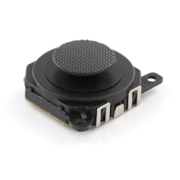
This is a resistive analog joystick, very similar to those found on the PSP1000. These compact joysticks are different in that they have a very interesting 'slide' feeling.
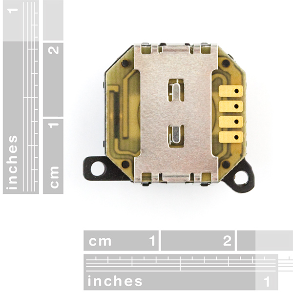
For wiring this part, if you look at the device from the bottom the pin out goes
- 1) x-axis output
- 2) +5V
- 3) y-axis output
- 4) gnd
Pin 4 is the pin closest to the 2 mounting tabs found on one side of the device. When connected to an Arduino, you can expect a range of about 128 to 775 on each axis.
The rubber thumb pad is removable if you desire.
The pads are spaced by 2mm, but it is possible to get our 2.54mm headers connected with a bit of bending.
Thumb Slide Joystick Product Help and Resources
Core Skill: Soldering
This skill defines how difficult the soldering is on a particular product. It might be a couple simple solder joints, or require special reflow tools.
Skill Level: Competent - You will encounter surface mount components and basic SMD soldering techniques are required.
See all skill levels
Core Skill: Electrical Prototyping
If it requires power, you need to know how much, what all the pins do, and how to hook it up. You may need to reference datasheets, schematics, and know the ins and outs of electronics.
Skill Level: Competent - You will be required to reference a datasheet or schematic to know how to use a component. Your knowledge of a datasheet will only require basic features like power requirements, pinouts, or communications type. Also, you may need a power supply that?s greater than 12V or more than 1A worth of current.
See all skill levels
Comments
Looking for answers to technical questions?
We welcome your comments and suggestions below. However, if you are looking for solutions to technical questions please see our Technical Assistance page.
Customer Reviews
3.5 out of 5
Based on 2 ratings:
2 of 2 found this helpful:
Great, when workding
I've bought a handful of these over the past couple of months and find them to be sometimes unreliable. Some will work great and others not at all. The contacts inside are also very sensitive to bending, even slightly, so take care if removing the PCB to do some soldering (soldering without removing the PCB is not a good idea, as the joystick can deform/melt).
Otherwise, when the are working, they are great because of their size and cool slide mechanism.
Sorry about the issues. If you ever have a bad part, please feel free to contact us via our returns form - https://www.sparkfun.com/returns
0 of 3 found this helpful:
Pin Out
The nub is up and facing you (so your face is parallel and hovering over the nub?). The pins on the bottom away from you and pointing to your chest (so your chest has been removed from your body so these pins can now point towards your chest as suggested because I assume they are still away from you). All sounds really uncomfortable. Technical writer... you are not.
As cool as I find Timmy's breakout board, what I really want is this joystick on a LilyPad. Is there a practical way to connect it to the LilyPad Protoboard Small? Or a way to put together a LilyPad version of Timmy's board?
(SparkFun: a LilyPad board with this on it would be brilliant!)
Hi there, it sounds like you are looking for technical assistance. Please use the link in the banner above, to get started with posting a topic in our forums. Our technical support team will do their best to assist you.
Unfortunately, I am not really sure what Timmy's breakout board is... I even tried to do a "Google" search. That being said, you probably won't find a LilyPad board with a joystick as the medium (fabric) isn't rigid enough to handle that. Your best option is to "hack" something together.
Does someone have 3d CAD for this part ? or CAd or any specs ?
this is an awesome little component, but I think I really need a breakout board to use it correctly now that I get my hands on it. Hope it's finished soon.
A breakout board would be great for this item!!!!!!!!
I uploaded a pretty simple one to my OSH Park profile that you can find here.
I haven't tested it myself, but I triple-checked the traces, dimensions and pins and everything seems to check out. You can verify the layers if you wish. You can get 3 of them for $7, so it's pretty cheap.
Second that. And a digital version (4 directions) of this would be nice.
I really see no need to a breakout board.
Is there going to be a breakout board for this part?
I've killed several of these by keeping my iron on the pads too long and the pad coming away with the solder and wire as it cools. It almost takes three hands to hold everything while someone else solders the connections. That or my skills are so lacking that I'd clearly be in the running for the Ugliest Solder Join at a competition... Either or, take care when prepairing to solder these.
I find myself wondering if it would be any easier to pull the PCB out of the unit to solder and then put everything back together when complete.
EDIT: Removing the metal clip allows you to pull the PCB off and it is somewhat easier to solder headers or wires in place. The PCB itself is very thin, you must take care with how long you leave the iron on the pads as thin PCB doesn't tollerate many solder attempts.
SparkFun, it'd be nice if breakout could be sorted out. Shouldn't be too hard with a reflow setup though.
For those who would really like to refer to an image for the pin out, this post would help. http://mechail.wordpress.com/2009/04/23/psp-joystick-project-part-one/
Bought this joystick to replace my broken one on the PSP 1000. Works great and was delivered in three days.
It says +5 volts, being analog will it work correctly with a supply of 3.3v ?
Thanks.
I just tried it at 3.3V, and yes, it works fine. Being resistive it should technically work at any (reasonable) voltage.
Is there a datasheet for this part, for those of us who don't use Eagle?
I'm thinking of mounting this to a custom PCB using copper tape (with conductive adhesive) and screws. Anyone know the best screws to use for this? Also, any tape suggestions? Sparkfun sells copper tape, but it doesn't look like its adhesive is conductive.
So I tried this out and like it, but does anyone have an idea of how to mount it? There are few screws small enough for those holes and I wouldn't even know how you would tap holes for screws that small.
Does anyone know what screws are meant to be used with this?
I bought a set of #2-56 screws here on SparkFun and tried them out with a circuit board designed using SparkFun's footprint of this part (according to it, the joystick holes are 2mm in diameter). They fit snugly (i.e. I could go without using a nut on the bottom side of the board), but they seem to work. If you want a looser fit, you'll need a hole bigger than 2mm in diameter on your board.
Also, the #2-56 screws here have good clearance regarding the heads and the body of the joystick. Moreover, they don't stick out too far on the bottom side of the board.
For a connection, I'm currently experimenting with copper tape. Optimally, you'd want conductive adhesive too. I bought this tape from SparkFun which apparently does not have conductive adhesive, and I am folding it over partially in order to have a fully conductive part and a part with adhesive on the underside, then placing it on the PCB pads. For an idea of the footprint, see TimmyTopHat's board from his comment above.
I did find that I needed a small nylon washer/spacer to place between the mounting hole on the joystick and the PCB drill hole (you'll notice upon inspecting the pic that it's not going to be flush with the board otherwise). The best fit I found was here from DigiKey. The height of this spacer should optimally be between about 1mm to 1.5875mm (1/16"). The spacer I found on DigiKey was about 5mm, so I cut it into quarters to achieve the desired spacer height. However, the inner and outer diameters of this spacer work great.
As a bonus, you could put a spacer on either side of the joystick mounting hole if you don't like how far the screw sticks out the back side of the PCB. Hope that helps!
Is there an eagle part for this?
Yes, in the SparkFun Eagle library
Just wondering, from the orientation of the product photo, what is the axis orientation on this? Like, from looking at the top with the mounting holes facing towards your chest, can I assume that sliding the pad UP will INCREASE the resistance on the Y-Axis output? And which direction will increase the X-Axis output?
How does it work
Good question - would have to take one apart* to see exactly how they have implemented it, but at the very least there's probably resistive tracks/pads or a single resistive pad in there - similar to a potentiometer - and if I had to guess some bits of plastic that are bent inward providing a spring effect that re-centers the slider for the most part (see other comments here about the return-to-zero position having a fair amount of slack).
( * Something I wish SFE would do for all products - who doesn't love a teardown? :) )
Edit: Oh, here we go. Repair a wandering PSP analog joystic. You can see that that version basically has two parallel track configurations, one for each axis. The sliders themselves are axis-limited, and the cap itself has the re-centering trick in the form of a metal spring - a bit more expensive, but less susceptible to fatigue.
How could i interface this with an Arduino Fio and a Series 1 Xbee? I'm relatively new to robots with joystick controllers, so any information would be great. I just need the Fio, the Xbee, and this joystick to make my controller if anyone wanted to know. ANY links, code examples, etc. are greatly appreciated.
Thanks, Nate
cool product
How well do these center?...or another way of saying it, is how well does it repeat center.
I need it to hold about 10-20 adc digits (unsure of proper language)
Can't find teh Eagle part... What's its name?
JOYSTICK-PSP1000
Awww.... Dammit. I need documentation for it's dimensions! Is there a doc sheet?
bought one of these about a year ago, still using some scrap RJ-11 cable to run it. Any word on a break out board?
just wondering, if i were to plug this to an AVR with some wiring, or headers, would I program it as a potentiometer or what? Another thing would you connect these to ADC or digital pins? Sorry I'm new at this.
It is an analog device. You plug it into an analog (ADC) pin.
Xbee radios have a 2mm header connector. That male header is not available here at sparkfun, but this is just to say that they are indeed readily available...
how similar are they to the ones found in the psp1000? would they make a decent drop-in replacement?
They feel very similar. I'm not sure about a drop in replacement though.
Has anyone connected one of these to an arduino yet? any notes?
I just did so, and the information in the description is incorrect (care to correct this, Sparkfun? And kudos that I got it as part of Free Day :) ). With the nub up and facing you, and the pins on the bottom away from you and pointing towards your chest, from left (pin 1) to right (pin 4):
1) x-axis output
2) +5V
3) y-axis output
4) gnd
Just to make sure I'm clear, my pin 4 is the one closest to the two screw/mounting holes. When connected to an Arduino, I get a range of about 128 to 775 on each axis, with enough consistency to check if it's at -x, center-x, +x, and -y, center-y, and +y. It has a fairly large range of "nominal" values when centered, but this isn't a problem for me since my application doesn't involve reading a range of values.
A further note on the consistency...it has sort of a hysteresis. Hooked up to an Arduino I get a range of about 240 to 800. If I release it from the 240 end, it returns to a "center" of about 430. If I release it from the 800 end, it returns to a "center" of about 600.
That's close enough for my needs, but if you want better consistency I found the Thumb Joystick sku: COM-09032 returns to a center with repeatability of plus or minus a count or two.
Kerm is right. I could not figure out what I was doing wrong with these until I scrolled down and read his comment. These things are super easy to use, as long as you don't follow SparkFun's pin configuration.
How tall is the joystick and how big a hole would it need for mounting? Can it be flush mounted?
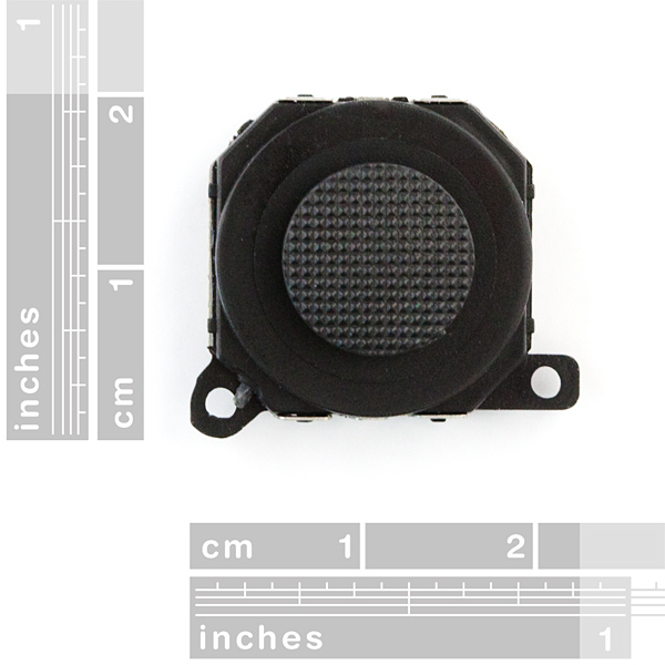
It's about 9.25mm from the bottom to the very top of the cap. It's a funky octagonal shape, but the max length from side to side is about 18.5mm. It could definitely be flush mounted.
-techsupport at sparkfun dot com
Hi, what is the resistor value of the joystick? I would assume something in the range of 1k-5k, can you specify that please?
Hi there,
Each axis is about 3.5-4k at the middle position, and they range from about 2k to 5k depending on the direction they're pushed.