- Home
- Product Categories
- Infrared
- SparkFun Line Sensor Breakout - QRE1113 (Digital)

SparkFun Line Sensor Breakout - QRE1113 (Digital)
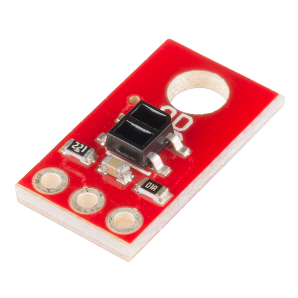
This version of the QRE1113 breakout board features a digital output, using a capacitor discharge circuit to measure the amount of reflection. This tiny board is perfect for line sensing when only digital I/O is available, and can be used in both 3.3V and 5V systems.
The board's QRE1113 IR reflectance sensor is comprised of two parts - an IR emitting LED and an IR sensitive phototransistor. When you apply power to the VCC and GND pins the IR LED inside the sensor will illuminate. A 100Ω resistor is on-board and placed in series with the LED to limit current. The output of the phototransistor is tied to a 10nF capacitor. The faster that capacitor discharges, the more reflective the surface is.
These sensors are widely used in line following robots. White surfaces reflect more light than black, so, when directed towards a white surface, the capacitor will discharge faster than it would when pointed towards a black surface.
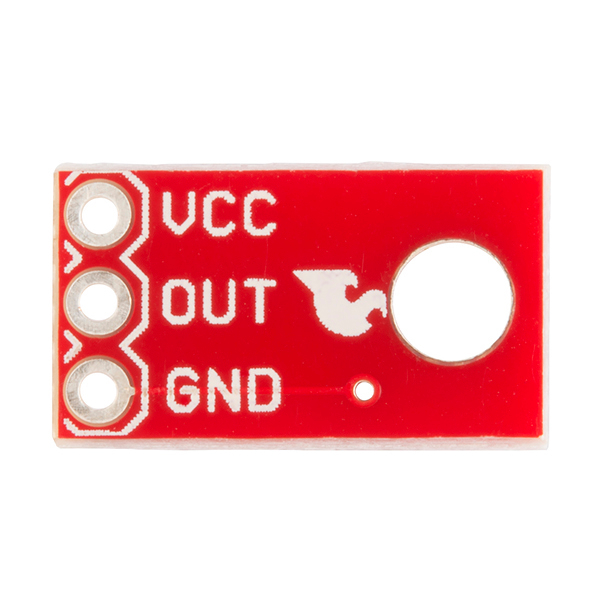
The power input and output pins are brought out to a 3-pin, 0.1" pitch header. The board also has a single mounting hole if you want to screw it onto something.
We also have an analog version of this board.
- 5VDC operating voltage
- 25mA supply current
- Digital I/O compatible
- No ADC required
- Optimal sensing distance: 0.125" (3mm)
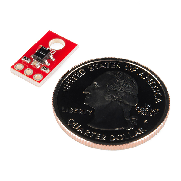
- 0.3x0.55"
- Schematic
- Eagle Files
- Datasheet (QRE1113)
- GitHub
SparkFun Line Sensor Breakout - QRE1113 (Digital) Product Help and Resources
Build a Qwiic Jukebox that is Toddler Approved!
March 29, 2019
Follow this tutorial to build your own custom jukebox. Note, this is designed simple and tough for use primarily with toddlers. It's also a great introduction to SparkFun's Qwiic products!
Core Skill: Soldering
This skill defines how difficult the soldering is on a particular product. It might be a couple simple solder joints, or require special reflow tools.
Skill Level: Noob - Some basic soldering is required, but it is limited to a just a few pins, basic through-hole soldering, and couple (if any) polarized components. A basic soldering iron is all you should need.
See all skill levels
Core Skill: Programming
If a board needs code or communicates somehow, you're going to need to know how to program or interface with it. The programming skill is all about communication and code.
Skill Level: Rookie - You will need a better fundamental understand of what code is, and how it works. You will be using beginner-level software and development tools like Arduino. You will be dealing directly with code, but numerous examples and libraries are available. Sensors or shields will communicate with serial or TTL.
See all skill levels
Core Skill: Electrical Prototyping
If it requires power, you need to know how much, what all the pins do, and how to hook it up. You may need to reference datasheets, schematics, and know the ins and outs of electronics.
Skill Level: Noob - You don't need to reference a datasheet, but you will need to know basic power requirements.
See all skill levels
Comments
Looking for answers to technical questions?
We welcome your comments and suggestions below. However, if you are looking for solutions to technical questions please see our Technical Assistance page.
Customer Reviews
4 out of 5
Based on 1 ratings:
Compact and works fine
Does what I expected it to do
Hi everybody. I am using the analog variant of this part as a reflective encoder on a motor and it works fine as long as the reflective and non reflective surfaces are different enough in reflectivity regarding the IR spectrum. I am quite happy with it for now but I would like to have lower low levels to have a little more margin. I was thinking about a separate schmitt trigger but I dont want to add another component to my circuitry. Then I saw this igital variant. However, I am really curious on how this one is supposed to work. with only a capacitor connected to Vcc the output will never go high, and if you apply a pull up resistor upstream of the output after the 200ohm resistor you will have an analog variant again with worse performance because you will have extra voltage drop accross the 200 ohms. so I would really like to see some scope shots of this actually working "digitally". Maybe I am missing something, but I feel that this breakout board is redundant or even less performant than the analog one.
I am happy to hear other peoples opinion on this
I just got one and gave it a run. I threw a 220KOhm pull-up on the output and it's basically an analog output, though with such a steep threshold that it may as well be digital. I personally view it as being more of an analog output, but it did the job for what I needed
I agree with your take on the so called "digital" variant. I looked at the schematic of the "analog" variant and the "digital" variant and it seems like the " analog" variant is actually the "digital" variant. I think that the supplier has these variants mixed up.
On Arduino:
void setup () { pinMode(9, INPUT_PULLUP); }
void loop () { int val = digitalRead(9); }
I think that the 100 ohm is not enough to limit the LED current to the nominal 20mA specified in the component datasheet when powering the sensor with 5V.
This value is correct for a 3V3 supply, and has been obviously selected for this configuration of use, but it is definitely too low for 5V. The resulting current is (5 - 1.2) / 100 = 38mA. Even if under the absolute maximum (50mA) it is prejudicial to the LED lifetime.
Conclusion : either mention that the board is designed for a 3V3 usage (hence not for an Arduino) or change the resistor. Apart if your goal is to have customers buy more units after having fried their first batch ;)
According to the datasheet the max continuous current is 50mA. A higher value resistor would likely be a good idea when using this with a 5V power but the 100 ohm resistor shouldn't burn out the device. Many of the specs in the datasheet are listed for a 20mA current but I don't think 20mA is required for the device to work correctly. (Sorry for the reply on a 5 year old comment.)
How can I use these with a raspberry pi?
You use the 100-Omh resistor in the IR-LED circuit. Are You sure that the 50 mA current (with 5 volt source) isn't too large for the QRE1113? IMHO, QRE1113 is too hot.
hey sparkers--the schematic and eagle file links are broken. Just FYI
Here is an Arduino library for reading Pololu's version of this sensor. It should work for the Sparkfun version as well.
Hi.
I had a some problem that you.
pulsein is good, but for me it had a problem with timeout. When sensor get a black floor, pulsein didn't return any value and "void loop()" was freezed waiting for value.
Now I used the code below:
pinMode( pinLine, OUTPUT );
digitalWrite( pinLine, HIGH );
delayMicroseconds( 50 );
pinMode( pinLine, INPUT );
// long readLine = pulseIn( pinLine, HIGH, 1000000L ); // wait max for 1 second.
long readLine = 0;
while ( digitalRead( pinLine ) == HIGH ) {
readLine++;
if ( readLine == 15 ) { break; }
delay( 20 );
}
In my case, 1 = white and 15 = black.
Actually, I think that should be pulseIn(xxx, HIGH);
Looking at the schematic, I assume that you have to set the digital I/O line high to charge the cap, then flip it to input and time how long it stays high, e.g.
pinMode(xxx, OUTPUT);
digitalWrite(xxx, HIGH);
delayMicroseconds(50); // 220 ohm * 1e-9 farads * fudgefactor
pinMode(xxx, INPUT);
int reading = pulseIn(xxx, LOW);