- Home
- Product Categories
- DC/Gearmotor Driver
- SparkFun Serial Controlled Motor Driver

SparkFun Serial Controlled Motor Driver
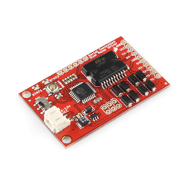
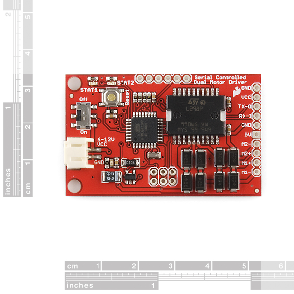
The SparkFun Serial Controlled Motor Driver allows you to control up to two DC motors using a serial command interface. The serial interface is easy to use and it lets the user select an individual motor, the direction, and the desired speed constant (up to 10 different speed from stop to full speed). The board is based on the L298 Dual Full-Bridge Motor Driver from ST Micro. The motor driver can provide up to 4 Amps of current to the motors (2 Amps per motor).
Power can be applied to either the two-pin JST connector or the GND and VCC header pins. Supplied power should be DC and within 5-16V. Please note, the pin labeled '5V' should only be used as an output.
The serial command interface used to control the motors is very straightforward. A command consists of four characters: the motor number, the direction indicator, the speed constant, and a carriage return. The baud rate of the Serial Controlled Motor Driver is set to 115200bps (8-N-1).
- Serially control two motors separately
- 115200bps (8-N-1)
- Very straightforward command set
- Drive up to 2A per motor (4A total)
- Speed control
- Forward/reverse control
- Over-current detection
- LEDs indicate over-current state
- Unused ATmega328 pins broken out for custom use
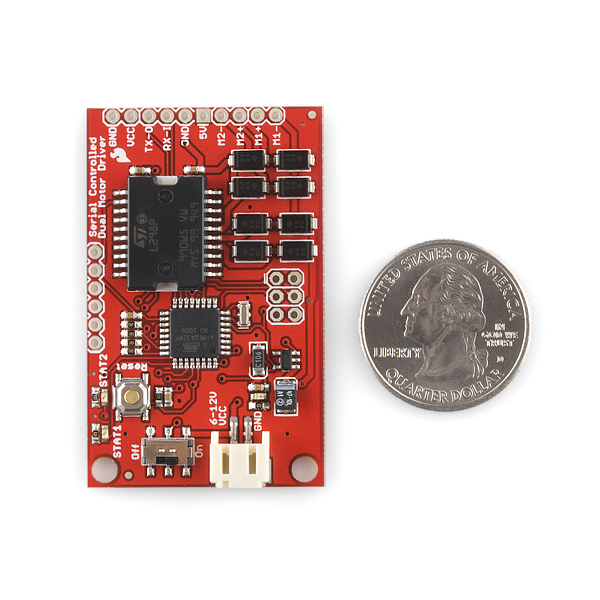
- 2.10 x 1.30 " (53.34 x 33.02 mm)
SparkFun Serial Controlled Motor Driver Product Help and Resources
Core Skill: Soldering
This skill defines how difficult the soldering is on a particular product. It might be a couple simple solder joints, or require special reflow tools.
Skill Level: Noob - Some basic soldering is required, but it is limited to a just a few pins, basic through-hole soldering, and couple (if any) polarized components. A basic soldering iron is all you should need.
See all skill levels
Core Skill: Robotics
This skill concerns mechanical and robotics knowledge. You may need to know how mechanical parts interact, how motors work, or how to use motor drivers and controllers.
Skill Level: Rookie - You will be required to know some basics about motors, basic motor drivers and how simple robotic motion can be accomplished.
See all skill levels
Core Skill: Programming
If a board needs code or communicates somehow, you're going to need to know how to program or interface with it. The programming skill is all about communication and code.
Skill Level: Rookie - You will need a better fundamental understand of what code is, and how it works. You will be using beginner-level software and development tools like Arduino. You will be dealing directly with code, but numerous examples and libraries are available. Sensors or shields will communicate with serial or TTL.
See all skill levels
Core Skill: Electrical Prototyping
If it requires power, you need to know how much, what all the pins do, and how to hook it up. You may need to reference datasheets, schematics, and know the ins and outs of electronics.
Skill Level: Noob - You don't need to reference a datasheet, but you will need to know basic power requirements.
See all skill levels
Comments
Looking for answers to technical questions?
We welcome your comments and suggestions below. However, if you are looking for solutions to technical questions please see our Technical Assistance page.
Customer Reviews
No reviews yet.
Why are mounting holes either non-existent, or just poorly thought out? I see nifty boards that would be nice to grab, but the majority of the time there is no thought put into mounting. I wish more hobby designers thought about mounting holes more like computer motherboard manufacturers. For instance, the holes have a good clearance from the edge of the PCB, other components, and indicating marks. There is enough clearance for the head of a screw and probably a washer without any worry of smashing a component, the thin PCB edge or covering part of the silk screen.
Maybe I'm missing something but those current sensing resistors appear to be a bit undersized. At a continuous 2A drive the power dissipated by each pair of 1 ohm resistors is (2A ^2) * 0.5 ohms = 2W. Each resistor should be rated for at least 1 watt.
I think the sensing resistors are above the Atmega and they appear to be 0603 packages. AFAIK, 0603's tend to dissipate between 0.1W to 0.25W.
Assuming a 0.25W resistor the maximum current drive is sqrt(0.25W / 0.5 ohms) = continuous 0.71A max per channel. Or about a 35% duty cycle at 2A.
I think your final calculation isn't quite right because it doesn't account for the two 1 Ohm resistors in parallel per channel, each of which will carry half the channel current. If the power rating is 0.25W per resistor, then the maximum current per resistor is sqrt(0.25W/1Ohm) = 0.5A, meaning each motor channel can output up to 1A before it exceeds the current-sense resistors' power ratings.
However, I wouldn't be surprised if the current sense resistors are rated for 0.1W (very common for 0603s), which would mean each channel can output a total of just 0.63A before exceeding the ratings, making the claim of 2A per motor rather misleading.
It would be awesome if the next version included inputs for two quadrature encoders, to allow for closed loop speed control and position reporting.
Actually I'm currently designing something like this for a project I did on Kickstarter. It's very similar in a lot of ways, though right now the plan is to control it with I2C (via another board), serial would be no problem to implement.
Good idea; we'll look into it.
Hi,
I have some modified firmware working;-
* (MISO, MOSI) and (PC4, PC5) reading from a quadrature encoder on the motor (the motor has a couple of flip-flops and nand gates that convert to direction and movement pulses).
Should be pretty easy to do the direction sense in the pin change interrupts :).
I dont know how to put the code up :(.
D
Hello,
Can you share your code ?
I'am searching a solution to drive 2 motor, quad and pid with this board... (and i'm bloking on the "no-interrupt-poll-method" to read encoder...)
Thanks a lot
Seb
There seem to be a number of questions here about command format. Of course you first want to be sure your link is configured for 1152000 bps. I'm sending my commands to the Motor Controller using the Software Serial library for the Arduino UNO board and all are coded similar to this: ss.print("1R8\r"); . Works fine.
I did find that it is a good idea to send the FIRST command in the sketch TWICE. Otherwise it was not always effective.
I have been designing something similar except is uses I2C to control the motors and uses a ATmega328 so I can just write arduino code to the other difference is I use 4 gpio pins to allow for i2C addressing. I would rather use a sparkfun part but serial is expensive I2C would be my choice as I can use two pins and send to multiple motor controllers and devices. any chance you guys might make a i2C version wouldn't take much just a update to the firmware and provide the ability to update an address byte if you have some eeprom space left. I just don't have the right skills to write that code, compile and flash the 168 chip. i see in the schematic it is already wired up with the i2c pins.
i think there is a problem with the firmware, the compiler says this:
Arduino: 1.5.6-r2 (Windows 7), Board: "Arduino Uno"
In file included from sketch_jul13a.ino:8: main.h:52: error: expected primary-expression before '.' token main.h:52: error: expected primary-expression before '.' token main.h:52: error: expected primary-expression before '.' token main.h:52: error: expected primary-expression before '.' token In file included from C:\Program Files (x86)\Arduino\hardware\arduino\avr\cores\arduino/Arduino.h:245, from sketch_jul13a.ino:13: C:\Program Files (x86)\Arduino\hardware\arduino\avr\variants\standard/pins_arduino.h:41: error: expected unqualified-id before numeric constant C:\Program Files (x86)\Arduino\hardware\arduino\avr\variants\standard/pins_arduino.h:42: error: expected unqualified-id before numeric constant C:\Program Files (x86)\Arduino\hardware\arduino\avr\variants\standard/pins_arduino.h:43: error: expected unqualified-id before numeric constant
This report would have more information with "Show verbose output during compilation" enabled in File > Preferences.
Is the firmware posted current? The makefile says the device is atmega168, but it is a atmega328(p?). The more troubling issue regards the ADC setup code. Let me know if I am reading this wrong. In ioinit(), you set the ADATE bit in ADCSRA, but do not set ADTS bits in ADCSRB to select the triggering mode. Why are you autotriggering when you need to start a new conversion after the current conversion has been read in the ADC ISR?
Hi to all, I bought a pair of this board, conneted the first to my rover and send command from terminal and it works. After try with a Python program that sends the same commands and the card goes up in smoke, I looked at the firmware and there are so many controls that can not see that a wrong command may have triggered the problem. Now I find myself with a broken board, what can I do?
One motor is spinning slower than the other. Is this the driver or the motor? They both have a speed constant of 5.
I think this motor driver is great. I am using this on the multi-chassis tank version with a big, salvaged heat sink. I stalled the motor by holding it and the overcurrent light never came on. It also kept going very strong after the stall.
Would the serial command look like this? mySerial.print('1' 'f' '2' '/r')
You enter the commands separately. Thanks TextualHealing.
What and how can the unused atmega pins be used for?
To use any of the open pins, you would need to reflash the firmware on the board over the ICSP header. Your ability to tap into the unused pins would also be limited by how well you can solder onto the pin pitch, as most of them are not broken out. Beyond that though, you can use them as you would for any other standard AtMega application - digital read/write, analog read, and pwm control.
Is flyback protection built in?
Ok first off has any one used this with something other than an ardrino? I'm using a MSP430FR5739, and the baud rate is definitly set for 115200 (tested with another serial device) and used an oscilloscope to test the tx pin of my mico to make sure it actually is sending the data, which it is. So for sure my micro is good BUT the motor driver does absolutly nothing, doesn't send anything back on the Tx line, the stat lights do nothing. the most i get is a red indicator light when i supply power. The only things i can say i notice are the tx pin of my micro starts high, then goes to 0 for a start bit, continues on with all the data, goes high for a stop bit, and stays high after. The board doesn't go 0-5V it goes 0-3.6V which according to TTL logic anything past 2.7V's is a high so that should still work. And that latter is there is no info in the data sheet about MSB or LSB frist. And if any ones says i need to flash the board, then it's simply going back cause i'm not also buying an ardrino to flash a board taht should come ready to go.
Hi! I'm also trying to use this driver with a MSP430F2274 and i'm getting the same thing as you are! Did you manage to solve your problem? I've also noticed that whenever I send a message to the motor driver, the micro controller doesn't do anything else, it just stops its regular operations.
Hey gents, new here. Got this thing to work without any problems.
Question: In the User's Guide it says
"The speed is entered with an ascii number anywhere in the range of 0 and 9. If '0' is ued for the speed, the motor will be stopped (and the direction indicator doesn't matter). If '9' is entered for the speed value, the motor will run at full speed. If any other speed value is used, the motor will receive a pulse width modulation signal to control the speed."
Any one know how I can specify speed value outside of 0-9? Or if it's even possible? Thank you much.
Why would you need a speed value outside 0-9
This little board worked a charm when using a 7.4v LiPo. Be careful when supplying more than 12 volts. When I supplied 14.8v the 47uF capacitor (C8) exploded. It's probably a max 16v capacitor. Also notice that the L298 on the board has no heat sink. It gets smoking hot when driving an RC car motor. I confess removing the overcurrent protection from the firmware. My conclusion, great little board. My suggestions to SF for a new version of the board are obvious, replace the capacitor and use a L298 with heatsink.
Hi there, I bought this motor from you and it has 4-wires which indicates that it is a Bipolar stepper motor. http://www.sparkfun.com/products/10848
I have also purchased this motor driver. How do I use this driver to drive the 4-wire bipolar motor? Thanks
Use a DC motor with this driver or get stepper driver like this one http://www.sparkfun.com/products/10267
Hello,
Has ANYONE got this thing to work?? I have copy and pasted some of the code provided here in this forum, but the compiler gives me an error signal unless I change the coding from:
Serial.write(‘1’); // to control motor 1
to:
Serial.write('1'); // to control motor 1
It's the apostrophe on each side of the 1 that has to be changed. I don't even know what to call the original symbols. Anyway, I have everything downloaded, but nothing happens. No motor, no voltage out, zip. I have two of these boards and nothing seems to work. Help!
I am answering myself here. I finally got my two controllers to work with the Arduino after flashing the serial motor controller firmware. What an adventure that was but the compiler ONLY worked when using the Duemilanove, not an UNO so be careful. The controllers will now work with the UNO. I followed the guidelines posted at this website: http://robotics-visionexperiments.blogspot.com/2010/10/re-programming-rob-09571-sparkfun.html
Unzip the Sparkfun files directly onto the C:/ drive to make everything easier in the command prompt arena. You may need the WinAVR compilier, but do all of the work in the Windows command prompt window and make sure your Arduino is running at 19,200 baud before doing anything else. Run the Arduino ISP program (in the "Examples" file of the Arduino software menu) first and go from there. Catch the right port number, etc...with every command prompt you cut and past from this website. You can switch the Arduino back.
how i upload the firmware to this, because i only have the main.c and .h files and arduino compiler is asking for pde files??
This is meant to be controlled over serial and does not have the Arduino bootloader on it.
can some one pls give me an example code for using with arduino?
This is meant to be controlled over serial and does not have the Arduino bootloader on it.
is there any reason I couldn't use an ISP to program this with the Arduin IDE?
Or even load a boot loader (using an ISP), break off the reset pin, and program it with a serial port just like any other Arduino?
This board is exactly what I am looking for but I have a codebase in Arduino. I don't see any reason to move it all over to WinAVR If I could just turn this little guy into an Arduino.
Any word on how to change this to the arduino IDE?
I need help!!!!
I just noticed in the serial monitor that if you code the Serial.print('\r'); then this will NOT print. It will print the / but not \ which seems to be a common post as a mistake by the user guide. Can someone help me with this? I am using an Arduino Mini Pro 5V w/ ATMega328. Here is my code. I did not comment it out.
void setup() { Serial.begin(115200); //set serial to 115200 baud rate } void loop() {
Serial.write('1'); Serial.write('f'); Serial.write('5'); Serial.write("\r"); Serial.println(); digitalWrite(13, HIGH); delay(2000); Serial.print('1'); Serial.print('r'); Serial.print('5'); Serial.print("\r"); Serial.println(); digitalWrite(13, LOW); delay(2000);
}
I should also mention i tried with Serial.print and Serial.write, neither worked.
Is this, serial controlled motor driver, compatible with arduino mega 2560?
I got it working with a Mega 2560 today without much trouble--Vcc at 6.0V from a dc-dc converter and tx/rx from Serial1 at 115200 baud. Having trouble though with the motor I'm using (from a Tamiya kit):
http://www.robotbuy.ca/products/Tamiya_6_Speed_Gearbox-346-9.html
http://www.mabuchi-motor.co.jp/en_US/cat_files/re_260ra.pdf
When power is applied to this motor from a standstill, a current spike of several amps occurs for about 500 microseconds which is enough to cause the overcurrent protection on this device to trip. It helps to read and print characters from Serial1 to see the error messages ("ALERT 150" or whatever which is supposedly about 1.5A).
Seems like it would be better if the firmware allowed greater current for a short period of time, so I'll have to reprogram it to be usable in this application. Still though, I'd have the problem of stall (or high load) current of this motor exceeding specs. Maybe another device is in order.
I've got mine working with an Arduino Mega even as I type, running off 4 AA cells, 6 volts; and using the Mega's 5V output to power the motor driver--to VCC input of the motor driver and NOT to the motor driver's 5V (which is output only).
You shouldn't use the 5v output of the mega because that uses the regulator and that can't handle the current needed for motors. You will kill the regulator on the mega.
Can this measure motor speed and return it via Serial?
Hi all,
I am trying to setup this board with netduino but no luck so far!
Based on user's guide it should be simple.
I've wired VCC/GND to the Vin/GND at netduino board (vin is 6V dc) TX/RX to D0/D1 (rx/tx) on netduino.
The code is something like this:
SerialPort com1 = new SerialPort("COM1", 115200, Parity.None, 8, StopBits.One);
com1.Open();
byte[] cmd = encoding.GetBytes("1f5\r");
com1.Write(cmd, 0, cmd.Length);
The should be ok, since I am using same for other serial components and its working fine.
There is no any activity on M1(+/-). always 0V.
Did anybody manage to run this board? Do I need to program board first or its already pre-loaded with firmware?
Thx,Ian
I finally got it working by using uppercase F & R NOT case insensitive as in the doco. ie
mySerial.print("1R5\r");
I had to reflash the firmware before I could get anything to work.
I have 3 of these. I think I'm doing everything right but nothing works. This is my arduino code:
#include
NewSoftSerial mcser = NewSoftSerial(2, 3);
void setup(){
mcser.begin(115200);
delay(1000);
}
void loop(){
mcser.print('1f5\r'); // to control motor 1
delay(2000);
}
as a query, could the voltage reset issue be solved by removing or cutting the output of the 5v reg, then tying the arduino 5v onto the motor driver board 5v "out" (making it an input for 5 v from an external regulated supply). Then running the arduino from a separate power supply to the vcc of the motor controller, eg a 9v battery wired to the arduino Vin.
cheers
I am thinking something similar as well. This board would be so perfect if it had separate motor power supply. I would like to power the motors directly from a Lithium Ion battery and remove the need for a step-up. Would be much better. I was thinking of just cutting the Vcc from the LM and connect the battery there, but your way might be better.
I got mine to work after flashing the most current firmware. They should be updating them now before shipping, but I am not sure.
Hi.
I am trying to make Ip Cam Rover somewhat like this ( http://letsmakerobots.com/node/22674 )
instead of using arduino, I used Serial Controlled Motor Driver.
there is foscam CGI command, comm_write.cgi which explained on this manual.
https://docs.google.com/uc?export=download&id=0B-yhhBvC0DSlNWExZDU0NTQtMDlmZi00YzkzLWFkNDAtMGU4MTA1MDg2YjMz
I am using this command to control my rover.
http://192.168.0.196/comm_write.cgi?port=0&baud=4098&bytes=4&data=1f4/r
but somehow it is not working.
I'd like to know what I am doing wrong.
Thanks
same with you,i fail to control a arduino car via the ipcam serial port,with comm_write.cgi command ,any suggestion to me,thanks
Hi. I just got a few of these for a project along with some motors, but I can't get it to work at all. I have everything wired up to an arduino and I have tried tx/rx and NewSoftSerial but I can not get a twitch or signal. I think it is a problem with communications because I don't seem to be sending anything or getting anything back. I have tried sending each character individually and sending them together but no luck. Anyone have any ideas?
For the life of me I can't get this thing to work. I reloaded the firmware since it would just turn on and both stat LED's would be lit. No matter what I do it won't turn the motors on.
I have it at 115200 and nothing. I get a ready on startup too. Whenever I send a command I get the command echoed back on the serial.
Any ideas?
are you sending a (return) as the last character?
do you see the status leds blink on each command?
from memory... (a few weeks since i played with orig software)
1f5(return)
2f5(return)
should turn on the motor driver to 50% power for both motors.
I saw some comments about the sense resistors here...
What are you using as sense resistors?
My applicatioon is sensitive to their characteristics.
In particular their stability at different tempretures.
And the maximum load I should expose them to.
I can work within most limits - but do need to understand them first.
Background:
I want to use the sensed current to infer the load on the motor - and hence the work being done..
I am trimming sails on a model boat, so the tension on the rope is a good control input:).
Regards,
D
As logictechs suggests, it's not too tricky to upload new firmware via an Arduino (http://robotics-visionexperiments.blogspot.com/2010/10/re-programming-rob-09571-sparkfun.html)
I received 2 of these a couple weeks ago. They were programmed with another version of firmware that is downloadable here. The motor fault lights stayed on but I was able to run motors and no fault was sent serially until I worked with my new Tamiya dual motor gear box from here also. I changed the overload value in the header file to 300 and was able to run the gear box. I also changed the code to accept a 'b' for setting both motors at the same time. Planning on making some animatronic props with them. Very happy with this product so far now!
A dip module for a next revision would be great -> no soldering required. Should change the layout / board dimensions but might be a nice alternative design to consider.
getting alerts at well under 1A, feeling a bit cheated, anything I can do to get anywhere near the claimed 2A? I only need 500-700mA.
I got the AVR programmer (Pocket Programmer for $15) and took out the limits and ran my motors from a voltage supply. The ALERTS show up even if you hit 1.5A. I have a feeling sparkfun wrote the code to limit it to 2A TOTAL. Whereas each channel can take 2A. We took out the limits and let the supply hit almost 3.5A and the controller works like a charm. So you just need to get the firmware and the programmer and change the ADC threshold to be something higher (I think they made it 150... which is around 1.5, so 3.5 is around 3.5A total).
YES, it's still a bummer that sparkfun still hasn't fixed this. But programming the board does have it's advantages... like now you can have some ADC pins you can use!
@ryowens84, I changed the baud rate to 115200 but still no success. I wasted my whole 2 days working to run this motor driver. It is just pissing me off!!!!!!!!
Have you tried communicating with the board directly through a COM port by removing the Arduino and using a level-shifter to verify that the commands you're using are valid?
You may want to contact tech support if your problems persist: techsupport@sparkfun.com
Hello Manufacturers!
Can anybody write a simple arduino code that can run a motor using the serial controlled dual motor driver coz i am having a lot of trouble using it.
Thanks a lot!
Anyone here??
Hello,
I am having trouble with using this serial controlled dual motor driver. I downloaded the User's guide listed above and accted on it. I have an arduino connected via USB to my PC and i connected the Tx/Rx pins of Arduino to the Rx/Tx pins of the motor driver I mentioned. I have connected my simple DC motor to the M1+/-. power 7V to VCC pin of motor driver and ground to GND pin. Here is the code that i am using:
void setup()
{
Serial.begin(9600); //set serial to 9600 baud rate
}
void loop()
{
Serial.write('1'); // to control motor 1
Serial.write('f'); // move in forward direction
Serial.write('9'); //run at full speed
Serial.write('/r');//
delay(2000);
}
Is there anything wrong with the code?. Also tell me whether we need to turn on the on-board power jack? Thank you for your help!
I stole that segment of code to try get started with and played around with it for about 10 hrs before I accidentally commentented out the '/r' and left a Serial.println, viola!
void setup()
{
Serial.begin(115200); //set serial to 115200 baud rate
}
void loop()
{
Serial.print('1'); // to control motor 1
Serial.print('f'); // move in forward direction
Serial.print('9'); //run at full speed
//Serial.print('/r');//
Serial.println();
//Serial.print('r');//
delay(2000);
thats just running straight off the arduino's serial pins, not in soft serial.
For debugging I found it helpful to put an LED one way round on the motor output and one the other so I would see results either way and could test a change in direction. I noticed also that theres seems to be a bleethrough from one of the serial pins, as soon as they were plugged on all the leds on the board and connected to it lit dimly.
actually that wont completely work. it will only set the first instruction and wont change, did some more playing and got it to work properly. the original code should be fine with one exception: the slash on the return carriage is the wrong way round. This meant that in the original version it wasnt finishing the command, and in my version it sort of finished it but not really since I had a new line but not a proper end carriage.
can you provide the full code for an arduino 2010? after the changes? thanks, just cant seem to find the right code.
void setup()
{
Serial.begin(115200); //set serial to 115200 baud rate
}
void loop()
{
Serial.print('1'); // to control motor 1
Serial.print('f'); // move in forward direction Serial.print('9'); //run at full speed
Serial.print('\r'); /"carriage return" note it IS the opposite way around to the rest of the slashes had me stuck for a while, I think its typo-ed in the user manual/
delay(1000); //just to make the code do something other than repeat the serial command over and over
this will set the arduino serial rate to 115200, send a full single channel instruction to the motor driver and then loop again. Copy that into an arduino sketch by itself and test it. To stop the motor again you will need to send a command telling that motor to run at "0" speed
Try setting the baud rate to 115200 instead of 9600.
Hi,how can I get new code onto the avr328?
You'll need an AVR Programmer and and AVR IDE (Integrated Development Environment). If you're used to Arduino then this is the next step. SparkFun sells several AVR Programmers:
http://www.sparkfun.com/commerce/product_info.php?products_id=9231
http://www.sparkfun.com/commerce/product_info.php?products_id=8702
http://www.sparkfun.com/commerce/product_info.php?products_id=14
If you get the last one, you'll also need this:
http://www.sparkfun.com/commerce/product_info.php?products_id=8508
My favorite is actually from Atmel, the AVRISP mkII:
http://search.digikey.com/scripts/DkSearch/dksus.dll?site=us)=en&mpart=ATAVRISP2=en&mpart=ATAVRISP2)
To learn a little about the AVR IDE called WinAVR, check out this tutorial:
http://www.sparkfun.com/commerce/tutorial_info.php?tutorials_id=93
I found this page - http://hlt.media.mit.edu/wiki/index.php/AVR_Programming - which shows an arduino being used as in ISP programmer for a ATMEGA-328 ... which looks good to me.
Would there be any way to slow down the baud rate so that communicating with this with an Arduino over Softserial at 9600 baud would be possible? Also, regardless of the motor state, the Stat1 and Stat2 lights are always on, I don't think that part of the code even exists or is functional.
Hello,
We'll take a look at changing the baud rate; perhaps we'll add a command to allow the rate to be changed in real-time. In the meantime, check out the library called NewSoftSerial by ladyada (http://www.ladyada.net/make/gpsshield/download.html). This will allow you to create serial connections at higher baud rates.
Also, you're probably correct about the Stat1 and Stat2 lights; I'll check that out later.
Any chance on having a tutorial for arduino's?
I agree that this would be a really useful tool. I bought two of these and they are both twitchy as can be. So far the first command is the only one I can get to take in serial mode. Tutorial would be helpful right about now...
when will it be in stock?
Nice board, but limited to 5V motors. Having separate Vs will allow up to 46V motors.
Actually the board will tolerate 12V motors. There is a 5V regulator, but that only supplies the logic levels for the motor driver, and the supply for the microcontroller. The driver voltage on the motor driver IC is equal to whatever input voltage is on the board.
12V is the maximum voltage because that is the upper limit of the 5V LDO.
the text description states "Supplied power should be DC and within 5-16V."
your comment states a 12v limit?
Which is correct?
My mistake. The voltage limit is 16V, not 12V.
Link to schematic appears to be broken.
Good catch! Fixed now.