- Home
- Product Categories
- Arduino Shields
- SparkFun Joystick Shield Kit

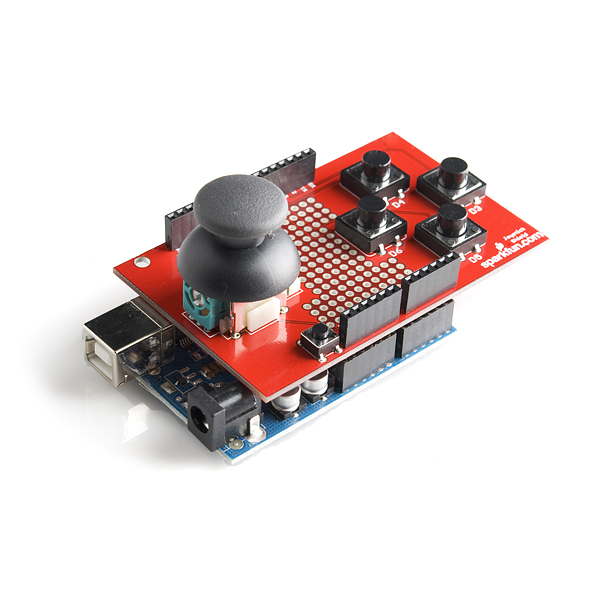
SparkFun Joystick Shield Kit
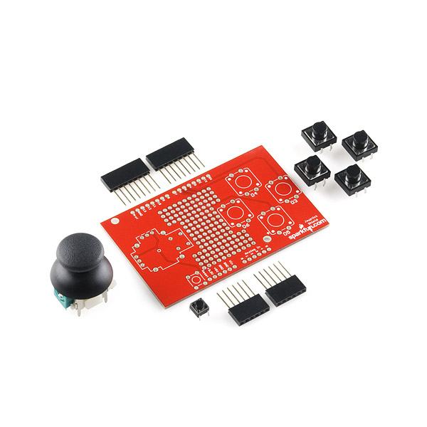
The SparkFun Joystick Shield Kit contains all the parts you need to enable your Arduino with a joystick! The shield sits on top of your Arduino and turns it into a simple controller. Five momentary push buttons (4+ joystick select button) and a two-axis thumb joystick gives your Arduino functionality on the level of old Nintendo controllers. Soldering is required, but it's relatively easy and requires minimal tools. We even have a step by step guide!
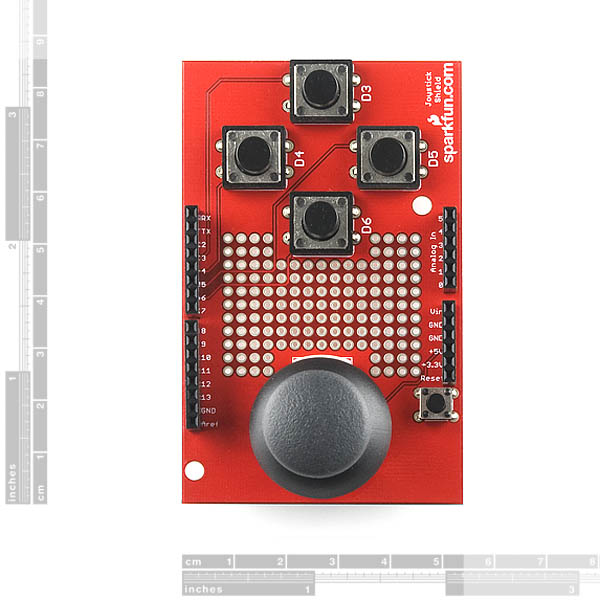
The momentary push buttons are connected to Arduino digital pins 2-6; when pressed they will pull the pin low (utilizing the internal pull-ups of the Arduino). Vertical movement of the joystick will produce a proportional analog voltage on analog pin 0, likewise, horizontal movement of the joystick can be tracked on analog pin 1.
- 1x Joystick Shield PCB
- 4x Momentary Push Button Switch - 12mm Square
- 1x Thumb Joystick
- 1x Mini Push Button Switch (breaks out Arduino's reset switch)
- 2x 6-pin Arduino Stackable Header
- 2x 8-pin Arduino Stackable Header
SparkFun Joystick Shield Kit Product Help and Resources
Thumb Joystick Hookup Guide
February 20, 2019
Whether you're blasting aliens, driving a robot, or write your awesome classic Arcade Game for your Arduino, you'll find the analog thumb joystick a very useful addition to your projects!
Core Skill: Soldering
This skill defines how difficult the soldering is on a particular product. It might be a couple simple solder joints, or require special reflow tools.
Skill Level: Rookie - The number of pins increases, and you will have to determine polarity of components and some of the components might be a bit trickier or close together. You might need solder wick or flux.
See all skill levels
Core Skill: Electrical Prototyping
If it requires power, you need to know how much, what all the pins do, and how to hook it up. You may need to reference datasheets, schematics, and know the ins and outs of electronics.
Skill Level: Rookie - You may be required to know a bit more about the component, such as orientation, or how to hook it up, in addition to power requirements. You will need to understand polarized components.
See all skill levels
Comments
Looking for answers to technical questions?
We welcome your comments and suggestions below. However, if you are looking for solutions to technical questions please see our Technical Assistance page.
Customer Reviews
4.5 out of 5
Based on 4 ratings:
3 of 3 found this helpful:
works great
No issues. I don't know what else there is to say.
2 of 3 found this helpful:
Great Little Shield!
Lots of options, expandable with the prototyping board.
Thanks sparkfun!
0 of 1 found this helpful:
Goodie
Handy, if perhaps bit bulky, but it works so no worries!
What about Microsoft make code
You set this up to run with arduino ,how about ESP32,all in ll a good kit,easy to assemble and works fine last long time.
RTM. This is a pre-order. Says so in the first line of the description.
you just got them listed and their already out of stock... ill need to check your site more often
This is a really nice little board, but it's killing me that it barely misses your nice project case: https://www.sparkfun.com/products/8601. It's just 5-6mm too long. So it looks like I have to break out the joystick/buttons, which is a shame. You could still keep the shield compatibility AND achieve project case compatibility if you trimmed a couple mm off of this thing.
I have created an Arduino library for this JoystickShield. You can find it out at http://sudarmuthu.com/arduino/joystickshield
Try it out and let me know if you have any feedback.
Are there any plans to update this for the R3 layout?
I'll look into it, but it isn't really necessary. None of the parts on the shield use the additional pins and the pass through feature is unnecessary as well since this is going to be a top level shield. I'm sure when this does get revised it will get an R3 layout, but that maybe a while.
I am using this code for my pan/tilt and it dances all over the place. Any suggestions??
If the servo is jittering (That is, it shakes a bunch and moves all over the place and doesn't do what it is coded to do) an easy solution is to add a capacitor. I had a servo controller attached to my arduino and it jittered because I was trying to drive too many without a separate power source. The capacitor fixes the issue.
here's one you can try
trying to use the example code for joystickmouse and the joystick shield but it is saying that Mouse is only supported on the leonardo can someone help me and yes i am using the r3 board please reply to this so i get a notification thanks
COULD I USE THIS ALONG with an xbbe and wirelessly control my robot? if so, how?
You would simply need to have the Arduino output the basic commands from the shield that you want to send over a serial line to your Xbee. There are a lot of example projects doing just this that you can see in our forum.
Try out this project for your joystick shield with processing:shurikenproject
it consists of using the joystick for moving a rotating shuriken on screen!
One on my buttons D3 won't reset after it's pressed. It's 1 until I press it and then it's 0 until I power it down. Ideas?
Are you using this shield with any other shields? if you are, you may have a pin conflict since button D3 is hard wired to pin 2.
Silk screen letters are upside down compared to Arduino Uno lettering. Does not affect functionality but it made me look twice. Other than that great board.
-Sam
I assembled my kit in order of component height: buttons, headers, joystick. The assembly instructions were easy to follow. At my son's suggestion, I substituted colored buttons from the Tactile Button Assortment, which gives my thumb some extra surface area to hit. The finished kit makes a great addition to our Arduino goodie box.
I used this with the XBee shield as a remote control for my lil robot:
http://ams-design.com/arduino/2011/09/the-spideruinos-controller/
Hopefully this will be helpful for someone! I know I could have used it ;) Full code provided on that page.
Cheers!
A
OK, we just assembled 200 of these for Gameduino, so here are some tips on assembly.
* do the headers first - they are tricky to get straight. It helps to have another shield that you can put the headers on, then push the joystick board onto the header pins.
* the joystick itself has 13 pins, and they are often bent. Get it roughly in place on the board, then use fine-tip tweezers to get the small pins lined up with their holes before gently pushing it down.
You should look into purchasing a board holder.
Please add a 3.3v/5v jumper for those of us who don't have 5v analog pins. tia
i want kit retail but its on back order im afraid to get this one that it wont come with all the parts needed
Two of the leads on the joystick are not long enough to poke all the way through the circuit board. I bought an extra joystick because of the written problems I read about in the comments and it looks the same way. How am I supposed to get a solder connection if the leads don't stick out?
Hmmmmm.....what if.....new layout...somewhere for the Atmel goodies on board, room for xbee to program it and communicate to some xbee modules on robot critters, Lipo for power.....the entire package could fit into an altoids can?
Is the prototyping area big enough to fit a second joystick and have enough room to move them without interference?
The joystick wouldn't fit into the prototyping are because the holes are too small for the large housing pins, the holes are only 2.54mm apart and the joystick doesn't conform to standard layout.
Also there isn't enough space to use another one comfortable on the board.
You could easily use the parts in the Sparkfun eagle library to make your own with two and get it made at BatchPCB
I have been working on a similar venture myself.
Would this be compatible with the Thumb Slide Joystick?
The footprint is for the Thumb Joystick, but you may be able to attach a Thumb Slide Joystick with some wires and solder.
No, just the thumb joystick in the related products below.
I had no problem assembling this, and the layout is nice, but the joystick turned out to be bad. When one axis was moved towards its extreme position the other axis changed value, even though there was no significant movement in the associated potentiometer. I took it apart, and the joystick in one axis directly controls its pot through the a direct connection to the lever, the other axis uses a cage mechanism around the lever that lets the lever slide through in one direction and moved the other pot when moved in the other axis. This cage seems to use the pot as is bearing point and I beleive that vertical movement in the cage is what caused the error. The other issue with the device is that it did not always "electrically reset" to its neutral position (as measuired with a multimeter) when release. I had to tap it or exercise the lever to get it to reset.
My advice it to check out the Joystick using an ohmmeter or equivalent before assembling the kit to make sure it is working properly. I am going to try another one to see if this was a fluke.
Aha! Respect fellas, I was going to suggest more holes. The other thing that is bending my mind is how to box the thing so I can use the thumb stick and have the buttons stick above the fascia of the enclosure. i.e. suitable for a user not a hacker.
And to be picky, extend the prototyping area to the button area, your positioning is probably generally excellent - but why constrain us when we are going to have to solder anyhow.
Just thoughts - thanks for all you do,
Glyn
what is the difference between this ant the retail kit?
The only difference between any of our retail products is the packaging. Retail kits or designed for retailers or distributors, or for gifts. There is no other difference.
oh i get it. i think retail kits makes more sense if i want to ship it via international shipping, am i right?
Not really, they will both ship with adequate packaging. It's just whether you want the plastic packaging or not.
just to point out till they update the photos:
the photos currently show the old revision.
the current revision has a prototyping area between the joystick and buttons.
you can already see it on the photos of the retail kit.
Awesome product, I need to get one bad, I got robots in my brain, they need to get out in the real world.
Sorry for the confusion. This is our first go at trying pre-sales.
For pre-sales, you should consider changing 'Add to Cart' to 'Preorder: Add to Cart' like Amazon does.