- Home
- Product Categories
- Imaging
- Light to Frequency Converter - TSL235R

Light to Frequency Converter - TSL235R
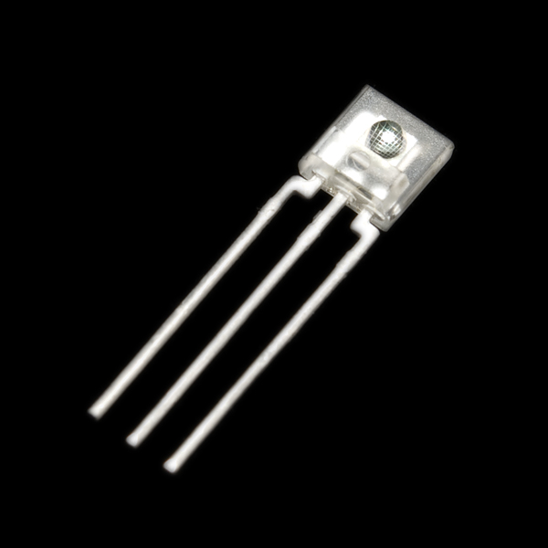
The TSL235R light-to-frequency converter outputs a square wave (50% duty cycle) with frequency directly proportional to light intensity (irradiance). The device has been temperature compensated for the ultraviolet-to-visible light range of 320 nm to 700 nm and responds over the light range of 320 nm to 1050 nm.
The TSL235R can be powered at anywhere between 2.7 and 5.5V, and will typically pull about 2mA of current. It comes in a simple, 3-pin through-hole package. No external components are necessary to use the converter, and the digital output allows direct interface to a microcontroller or other logic circuitry.
- High-resolution conversion of light intensity to frequency with no external components
- Communicates directly with a microcontroller
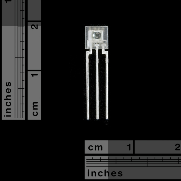
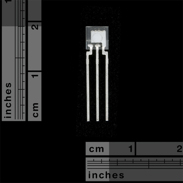
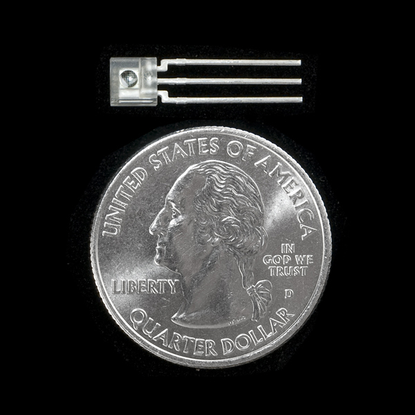
- Compact three-leaded clear-plastic package
- Single-supply operation down to 2.7 V
- Nonlinearity error typically 0.2% at 100kHz
- Stable 150 ppm/°C temperature coefficient
- Single-supply operation
Light to Frequency Converter - TSL235R Product Help and Resources
Core Skill: Programming
If a board needs code or communicates somehow, you're going to need to know how to program or interface with it. The programming skill is all about communication and code.
Skill Level: Rookie - You will need a better fundamental understand of what code is, and how it works. You will be using beginner-level software and development tools like Arduino. You will be dealing directly with code, but numerous examples and libraries are available. Sensors or shields will communicate with serial or TTL.
See all skill levels
Core Skill: Electrical Prototyping
If it requires power, you need to know how much, what all the pins do, and how to hook it up. You may need to reference datasheets, schematics, and know the ins and outs of electronics.
Skill Level: Noob - You don't need to reference a datasheet, but you will need to know basic power requirements.
See all skill levels
Comments
Looking for answers to technical questions?
We welcome your comments and suggestions below. However, if you are looking for solutions to technical questions please see our Technical Assistance page.
Customer Reviews
No reviews yet.
.
"Power-supply lines must be decoupled by a 0.01-uF to 0.1-uF capacitor with short leads placed close to the TSL235R." So I guess a capacitor is required to use this. That doesn't count as an external component?
Has anyone tried this at the low end of light intensity? Specifically, I'm trying to measure moonlight intensity (typically <1 lux).
What intrigues me is that moon planting and vine cutting supposedly give best results . Now if its so hard to sense these light levels electronically then what chance the plant even notices this . I'm working on the same area as you but I'm a bit behind you I think . If I get anything going I will post back here.
I've used a Silonex NSL-5540 successfully for moonlight applications.
I seem to be having trouble getting a valid frequency output from this device. I have it breadboarded and interfaced with an Uno Rev 3, 5V power, capacitor to decouple, GND, and input to Pin 2. I am using an interrupt routine to derive the frequency (per web examples). However, the values I get are in the 100 to 200 KHz range in ambient room light. When I move my desk lamp within 1 foot, the Arduino output locks up until I move the light away. Frequency readings when I do this exceed 300 KHz. Help! Is this an issue with the interrupt routine?
Getting Started with the TSL230R Sensor
So.. is the photocell about 1mm squared? Also, the datasheet mentions a lens on this unit. Does anyone know what the focal length of the lens is?
Yes, as per the datasheet: "The integrated photodiode active area is typically 0.92 mm2 in size". Say it's perfectly square, it might be 0.96mm x 0.96mm.
Nope. But you could calculate it. From the datasheet it's given that the lens is a hemisphere and the refractive index of the material is 1.55 . Performance would be an estimation as the rest of the body, while 'frosted', undoubtedly affects this.
Hi Everyone - do you think this sensor would work to differentiate a red and green laser (both about 5mW power)? Thanks so much
yes, easily
I think there is something quite wrong with these sensors. I have likely destroyed three... I know one is burnt out from 5 minutes in direct sunlight (no warning in the datasheet about this...) and the other two have failed to have even remotely recognisable output on the oscilloscope.
Similarly with arduino, the timer and the pin 5 FreqCounter lib won't work as the output is nothing like the square wave in the doco.
Heading back to the photodiode now, then after that fails the good old LDR... At least you KNOW an LDR will work...
Sam, @samotage
Whats the difference between the TSL235R and the TSL12S-LF...?
There's several differences, but the biggest is that the 235 outputs a fixed voltage at a frequency (square wave with 50% duty cycle) corresponding to the light level, while the 12S outputs a variable voltage.
what's the highest intensity this could measure? would it be able to measure full direct sunlight, or would it cap off before then? Could you maybe adjust the range?
You can always adjust the range using a filter, though you would have to find some other method of correlating lighting values to the frequency as a calibration step.
If I just go by the datasheet, page 2, Operating Characteristics at 5V, 25°C, it mentions that when it's completely dark (0µW/cm²) it outputs anywhere between 0.4Hz and 10Hz. So let's say total darkness is the bottom end of the range.
There's also a figure there that says "Full-scale frequency" with a note marker. The note marker explanations state "Full-scale frequency is the maximum operating frequency of the device without saturation". While this isn't an exact answer (saturation characteristics aren't defined) we can safely assume that they mean anything above the given figure - 500kHz - is a no-go area.
On page 3 there's an Output Frequency vs Irradiance graph. The values are presented on a logarithmic scale, so you can see that the graph does not go all the way up to 1000khZ, but stops at ~500kHz (the full-scale frequency value).
Going down the graph you end up at roughly ~~720µW/cm² or 0.72W/cm², or 7200W/m².~~
720µW/cm² or 0.72mW/cm², or 7.2W/m²
Values for sunlight are a bit scattered across the interwebs, but let's go with a NASA figure of 1361W/m². I'd say full sunlight is ~~well-covered~~ not quite covered. So you would have to use a filter and calibrate accordingly.
@Kamiquasi : Thanks for your really clear explanation EXCEPT that 720µW/cm² = 0.72mW/cm² = 7.2W/m² but not 0.72W/cm² nor 7200W/m². And of course it changes everything as the real input light density it can use is only 0.53% of the full sunlight density (of an averaged 1361W/m² indeed).
Whoops - totally right! What a difference a little 'm' makes.
Just a brief explanation of why you would use this guy:
For a blackbody (an object that emits what it absorbs with pretty good efficiency) the the peak wavelength emitted multiplied by the temperature of the object is equal to 0.2898 degrees Kelvin. Essentially this means that, from the frequency you can get wavelength and from the wavelength, you can get temperature.
This sensor basically measures intensity really well and does the dirty work to turn that into a frequency. (Intensity = sigma (a constant) x Temperature to the fourth power, and, using the above relationship, you can figure out the frequency it is emitting). You can therefore backtrack from the frequency you get to figure out the intensity.
Interestingly enough, in a roundabout way, this whole physical shebang is what led to pretty much all of Einstein's theories.
Practically, this means that you can tell the temperature of a blackbody (basically, anything that isn't a cloud of rarified gas or a mazer) by looking at it.
I think you misunderstand what this device does. It is a light /intensity/ sensor. it does not measure the peak frequency of received light.
This device measures light intensity and outputs a square wave whose frequency is directly proportional to light intensity.
This device has two impressive properties that may make it useful for any particular project. One is its huge dynamic range the other is its extremely good sensitivity if you integrate long enough it can rival the sensitivity of an expensive photodiode.
This would be true if the device had infinite bandwidth, but it's a purely optical device which can resolve relative illumination levels over a color range of 320nm (near UV) to 1050nm (near IR).
Any equivalent rated to -40C?
TSL237T. Its a fairly tiny surface mount though. I bought one and my weak soldering skills are not helping. It and the TSL45313 (ambient light, up to full daylight!) could use a breakout, as the TSL45313 probably can't be hand soldered.
I found an Arduino Frequency counter library: http://interface.khm.de/index.php/lab/experiments/arduino-frequency-counter-library/ I decided to forgo using their pre-amp circuit since the TSL235R has one built-in. I connected pin 1 to gnd, pin 2 to 3.3v, and pin 3 on the TSL to digital pin 5 on my arduino. Then I uploaded the example sketch from the site and it worked like a charm. The output seems to be fairly repeatable, the measurement of my room is ~1685, if I place my hand over it it outputs ~170, and then jumps back up to ~1685 pretty quick when I remove my hand.
Im not that good at this maths stuff. But can someone tell me how to get a rough (not too rough) lux reading from this. What maths would I have to perform on the frequency in 1 second (or another duration, you tell me).
I am using a PICAXE microcontroller, so whole numbers only in the maths.
lux is a measure of intensity that is weighted against the human eye's sensitivity. So unless you make some assumptions about the color of light or use a spectrophotometer you can't measure lux. OTOH if you read the datasheet you can see that irradiance is approximately 1uW/cm^2 per khz
can this be read by an analog pin?
Hey, how fast is this sensor? I mean, how many time beween readings?
By the way, Datasheet link is not working.
How much current could you run through this thing? 0.5A? That might be enough to drive a small gearmotor...
Max supply current is 3mA according to the datasheet. I'd believe that, I hooked it directly to 5v before I read the manual and got to smell that wonderful burning component aroma. Good thing I bought two of them.
Could you plz tell me how to wire this up then? I only have one so I don't want to blow it. I am using a PICAXE microcontroller with 5V power source. The datasheet diagram just has it hooked up directly to power supply like you said not to do. Only other component in datasheet is a 0.1uF capacitor, no resistors.
Or were you talking about max current through the data line? And it is fine to connect the GND and VDD pins straight to 5V?
I pulled a bunch of these out of an HP printer. They use them to position the printer head over the paper accurately. They use a strip of plastic about quarter inch high, and as wide as the printer with really thin vertical lines all over it to generate the light frequency. They also had a round disk to position the paper. So that's one application.
could this sense fire at close range like 1ft?
That depends on the fire. If it were ThinkGeek Timmy's Blowtorch KillItWithFire Fire or just a bright flame, probably yes. Also, LEDs output a small amount of power when exposed to bright light.
ok thanks, that page has helped a bunch.
how can one grab the frequency every second or so and store it in a variable for comparison. assuming its hooked up right to the 5v line and digital input on an arduino.
This might help:
http://roamingdrone.wordpress.com/2008/11/13/arduino-and-the-taos-tsl230r-light-sensor-getting-started/
It refers to the "full" IC but if you ignore the frequency scaling and "range" it is pretty much the same.
He uses an interrupt to count the pulses and get the frequency.
ooooh, optical theremin?
Hey, that would probably work! Simply connect to a speaker... I think I'll try it!
Quick Preview of the TSL235R, trying out the optical theremin idea.
Result: ehh, not so much... most of the frequencies you get waving your hand in front of it are quite high and annoying. So while it does work as a theremin, it's wouldn't be practical as a theremin, unless you added a frequency divider or something.
So what's the benefit to this device over a standard old photodetector? Spend more money? More accurate? I like PWM more than voltage differential? Drive something direct with it?
This device allows you to sense the light intensity with MUCH greater precision. It outputs a frequency between about 100Hz and 100kHz which is logarithmically related to the light intensity, as opposed to a 0-3.3V signal. Whereas your typical A/D gives you 8-10 bits of info, and thus 256-1024 datapoints, the accuracy of this chip is limited only by how many edges you want to count before your timer (or edge counter) overflows.
Can this device detect IR Light as well? There's a project I'm working on which I would like to detect the intensity of the IR LEDs bouncing off a wall - depending on the value returned it would dim the IR LEDS. Thanks for the response buddy!
Actually, the output frequency is linearly proportional(ignoring the tiny offset) to iridescence (power-per-area) in the range of 1Hz-1MHz. This means you can read light levels across six orders of magnitude. It's tough to read three orders of magnitude out of a typical photodiode.
I'm trying to use a photoresistor or photocell to detect pulse in the wrist - this light sensor looks like it might work for that, should I order?
This will actually work perfect for a SpO2 meter. The best IR wavelength to use is 950 nm, you would shine the IR through the finger/wrist and record the result. Then you would shine a bright red LED through the same area and compute the ratio between the two results. You do this since oxyhemoglobin has no resistance to IR but does have a computable resistance to red light. More explained here: http://www.equipmentexplained.com/physics/respi_measurements/oxygen/oximeter/pulse_oximeter.html
hi friend im using 660nm and 940nm to make a pulse oximeter,but im doubt about how to use TSL235R to get the spo2 from the frequency.could you tell me something more? thanks in advance~
I had the same idea - a DIY pulse oximeter. If anyone knows of existing designs, please let me know. I plan to connect this sensor to a "teensy" arduino-compatible board, shine a white LED on one side of a finger and this sensor on the other. If I can get heart rate from that, great! If I can get oxygen levels, even better though I suspect thats much harder to deduced from the input data.
Yes, this part would work quite well. I suggest shining the light through a finger instead - this is how pulse oximeters work. The best wavelength is between 800nm and 940nm, since you want to look for changes in oxyhemoglobin. See (http://en.wikipedia.org/wiki/File:Hemoglobin_extinction.png)