- Home
- Product Categories
- Arduino Shields
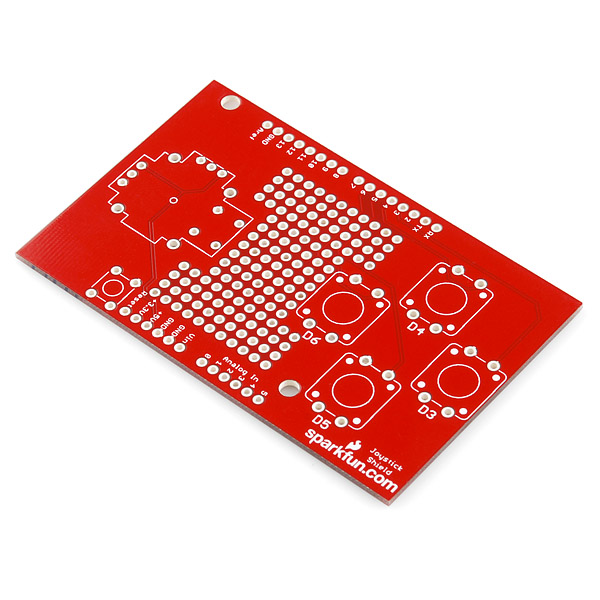
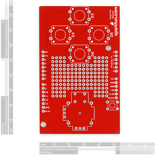
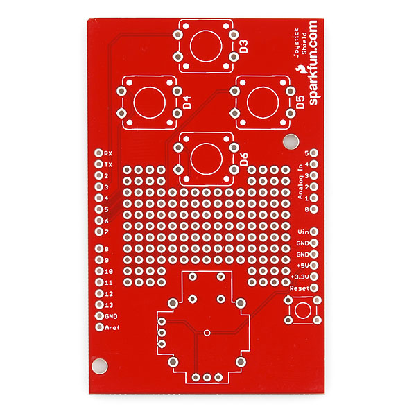
- SparkFun Joystick Shield - Bare PCB

SparkFun Joystick Shield - Bare PCB
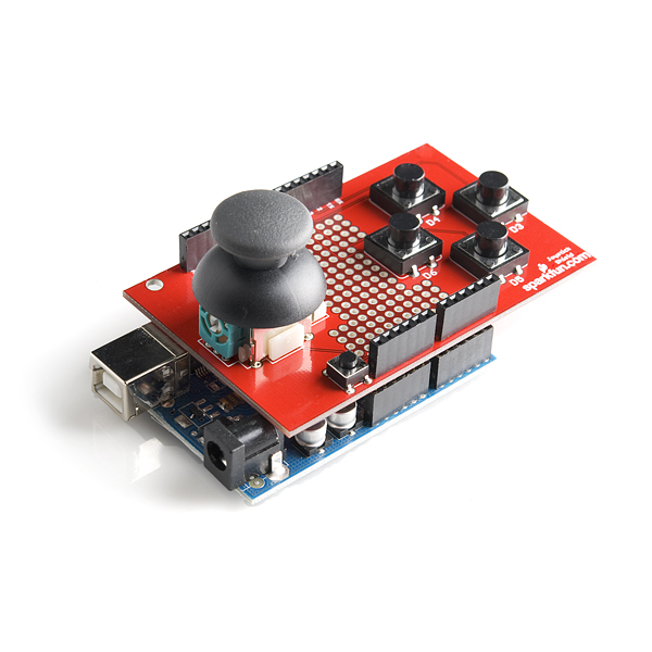
The Joystick Shield sits on top of your Arduino and turns it into a simple controller. Five momentary push buttons (4+ joystick select button) and a two-axis thumb joystick gives your Arduino functionality on the level of old Nintendo controllers.
The momentary push buttons are connected to Arduino digital pins 2-6; when pressed they will pull the pin low. Vertical movement of the joystick will produce a proportional analog voltage on analog pin 0, likewise, horizontal movement of the joystick can be tracked on analog pin 1.
This product is only the Joystick Shield PCB - you'll need to purchase the buttons and joystick separately, and assemble the controller yourself. Here's what you'll need in addition to the shield:
- 4x Momentary Push Button Switch - 12mm Square
- 1x Thumb Joystick
- 1x Mini Push Button Switch (breaks out Arduino's reset switch)
- 2x 6-pin Arduino Stackable Header
- 2x 8-pin Arduino Stackable Header
SparkFun Joystick Shield - Bare PCB Product Help and Resources
Thumb Joystick Hookup Guide
February 20, 2019
Whether you're blasting aliens, driving a robot, or write your awesome classic Arcade Game for your Arduino, you'll find the analog thumb joystick a very useful addition to your projects!
Core Skill: Soldering
This skill defines how difficult the soldering is on a particular product. It might be a couple simple solder joints, or require special reflow tools.
Skill Level: Rookie - The number of pins increases, and you will have to determine polarity of components and some of the components might be a bit trickier or close together. You might need solder wick or flux.
See all skill levels
Comments
Looking for answers to technical questions?
We welcome your comments and suggestions below. However, if you are looking for solutions to technical questions please see our Technical Assistance page.
Customer Reviews
4 out of 5
Based on 1 ratings:
Well Made PCB
No complaints
SPARKFUN: Why is there only one joystick. How am I supposed to control my robot with this. I hate using buttons to move around.
Buy two?
How do you suppose I put that on the shield? It was a suggestion for future upgrade.
You could use the prototyping area on this shield to attach one of these and a secondary joystick. Like mentioned in the description, this specifically was designed for those of us who enjoy the old-school, limited robot control of the Super Nintendo controllers.
Again, just a suggestion for another product or future upgrade.
And we definitely appreciate it! That was simply meant to be a helpful comment as to how you could modify the board as-is for your purposes. We try to design things to work for the largest majority, but with our awesome and varied customer base, there are always going to be use cases that our boards don't work for out of the box.
I know haha. Thank's Toni for your time! Can't please everyone. :)
Question: Why is the SEL button and button D3 set to Digital pins 2 and 3? This creates pin conflicts with the default configuration of many other shield boards, like the XBee shield board. At the very least this board should have started at digital pin 4 (using digital pins 4-9).
Suggestion: wouldn't it be better to have the Joystick shield designed more like the Xbee shield? Such that there was a solder jumper which could be cut for each button, so that all buttons could be easily remapped to any pins by soldering in wires. (the XBee shield has some great design principles applied to it, design principles which should be applied to every shield)