- Home
- Product Categories
- RTC
- SparkFun Real Time Clock Module

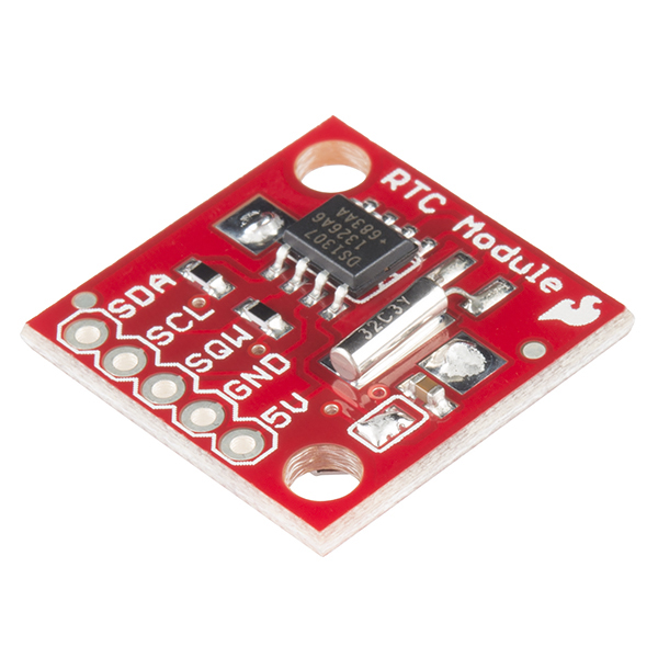
This is the SparkFun Real Time Clock (RTC) Module, this little breakout that uses the DS1307 to keep track of the current year, month, day as well as the current time. The module comes fully assembled and includes a small CR1225 Lithium coin cell battery that will run the RTC for a minimum of 9 years (17 years typical) without an external 5V power supply.
The DS1307 RTC is accessed via the I2C protocol. We've written a test-bed to program the modules, this code should give you some insight on how to interface the module to any microcontroller using our example software I2C and BCD routines.
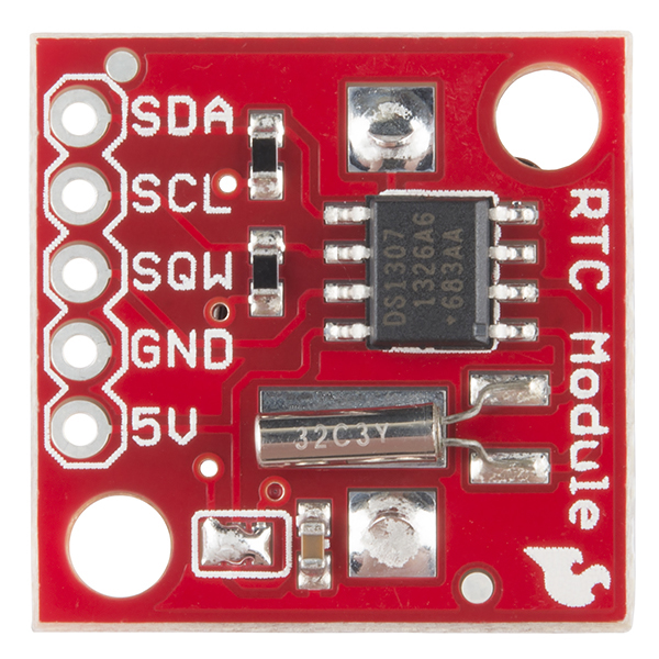
This rev of the Real Time Clock module finally adds I2C resistors and a larger battery pad to fix the problems with the battery shorting to the board.
- Two wire I2C interface
- Hour : Minutes : Seconds AM/PM
- Day Month, Date - Year
- Leap year compensation
- Accurate calendar up to year 2100
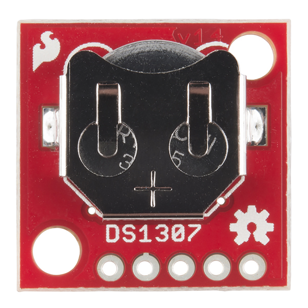
- Battery backup included
- 1Hz output pin
- 56 Bytes of Non-volatile memory available to user
- 0x68 I2C Address
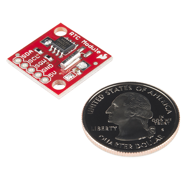
- 0.75x0.75" (20x20mm)
- Schematic
- Eagle Files
- Hookup Guide
- Datasheet (DS1307)
- Arduino Library
- Wiring Example
- Example 16F88 code
- Arduino Tutorial (Portuguese) Thanks Daniel Gonçalves!
- Bildr Tutorial
- GitHub (Design Files)
SparkFun Real Time Clock Module Product Help and Resources
Real Time Clock Module Hookup Guide
October 6, 2016
A quick introduction to the DS1307 RTC module and a hookup guide for the SparkFun Breakout.
Getting Started with the SmartLED Shield for Teensy
November 9, 2018
In this tutorial, we will connect different RGB LED matrix panels to PixelMatix's SmartLED shield and Teensy.
Using the RTC with 3.3V Systems
The supply voltage for the RTC DS1307 needs to have a 5V input so it is not directly compatible with a 3.3V device (like a 3.3V Arduino or a Raspberry Pi). You would need to do some modifications before being able to use it with a 3.3V system.
3.3V Arduino
You might be able to get away with just connecting the RTC to your 3.3V Arduino because of the open drain drivers => https://learn.sparkfun.com/tutorials/i2c#i2c-at-the-hardware-level . Otherwise, you might want to use a dedicated I2C logic level converter for the I2C pins => https://www.sparkfun.com/products/11955 . For the SQW pin, we recommend doing using a logic level converter https://www.sparkfun.com/products/12009 or voltage divider since the I/O of the Arduino is 3.3V.
Raspberry Pi
For a Raspberry Pi, you can remove the solder jumpers for the pull-up resistors so that you can just use the Raspberry Pi’s internal pull-up resistors. For the SQW pin, we recommend doing using a logic level converter https://www.sparkfun.com/products/12009 since the GPIO for the Raspberry Pi is 3.3V.
I2C Locking Up?
Arduino I2C appears to lock sometimes when trying to communicate with the DS1307. There is a modified I2C library here to detect when this happens and resets the clock => http://www.paulodowd.com/2015/04/ds1307-woes-i2c-freezes-and-locks.html
Core Skill: Soldering
This skill defines how difficult the soldering is on a particular product. It might be a couple simple solder joints, or require special reflow tools.
Skill Level: Noob - Some basic soldering is required, but it is limited to a just a few pins, basic through-hole soldering, and couple (if any) polarized components. A basic soldering iron is all you should need.
See all skill levels
Core Skill: Programming
If a board needs code or communicates somehow, you're going to need to know how to program or interface with it. The programming skill is all about communication and code.
Skill Level: Competent - The toolchain for programming is a bit more complex and will examples may not be explicitly provided for you. You will be required to have a fundamental knowledge of programming and be required to provide your own code. You may need to modify existing libraries or code to work with your specific hardware. Sensor and hardware interfaces will be SPI or I2C.
See all skill levels
Core Skill: Electrical Prototyping
If it requires power, you need to know how much, what all the pins do, and how to hook it up. You may need to reference datasheets, schematics, and know the ins and outs of electronics.
Skill Level: Rookie - You may be required to know a bit more about the component, such as orientation, or how to hook it up, in addition to power requirements. You will need to understand polarized components.
See all skill levels
Comments
Looking for answers to technical questions?
We welcome your comments and suggestions below. However, if you are looking for solutions to technical questions please see our Technical Assistance page.
Customer Reviews
4.4 out of 5
Based on 18 ratings:
2 of 2 found this helpful:
something you need
NOBODY told me you had to SET THE CLOCK !!!! There was a lot about it was set at the factory and would go for 17 years, but nothing about that I had to set the clock. I found it in an obscure tutorial on the use of PICAXE and the I2C serial communication protocol. Please note on your SPARKFUN data spec that the breakout board has to have the data SET with a HI2COUT instruction !
1 of 1 found this helpful:
Good clock!
Easy to use, I needed to set the clock too but it is easily accomplished with one line from RTClib (google it)!
1 of 1 found this helpful:
Awesome Product, but Lacking the Awesome SparkFun HookUp Guide
Preferred this over the "Dead On RTC", as the I2C is easier to connect than the SPI on the ICSP for the boards i use. The product worked as intended out of the box. The clock may have been programmed, but i didn't check. Piece of cake!
Being a thickheaded lout, the (typically awesome) SparkFun hookup guide would have been helpful to me. Still, i muddled through. I did use the AdaFruit branch of the JeeLabs library. (So i owe those folks.)
1 of 1 found this helpful:
Really nice time keeping chip but requires some understanding from other websites.
I have used this chip twice with an Arduino Uno: (1) To adjust the elevation angle of a pole mounted Solar array, and (2) To inject a specified amount of EM1 algae control solution into a grey water tank. Both projects required knowledge of real time (Month, Day, and Time). The chip itself is easy to use but requires some understanding of its internal programming and its I2C register assignments. The best source of understanding that I have found is an archived article from Hobby Robotics titled "An I2C Bus Example Using the DS1307 Real-Time Clock". This article, and its large number of following questions/answers, can be found at http://www.glacialwanderer.com/hobbyrobotics. This article, written by Maurice Ribble, provided all I needed to know about programming the chip and reading it's registers. Two words of advice to other novice users: (1) Don't use the square wave (SQW) output capability unless you actually need it. The chip's on-board battery lifetime is significantly reduced if you enable this function. (2) The chip's internal programming regularly outputs to 7 register locations that include second, minute, hour, dayOfWeek, dayOfMonth, month, and year (in that order). You can not change (or delete) the information loaded into each of these register locations. If you do not need all of that stored information for your intended purposes, simply modify your "get" program and request only what you need by name. For instance, you may not need dayOfWeek, but you must at least initialize this register when you are setting the starting time. (Be sure to comment out the initialization statement in your program after you have properly set time within the chip. Otherwise, when Arduino reboots (perhaps due to a power outage), the chip will be reinitialized to an incorrect starting time/date.)
1 of 1 found this helpful:
a good clock with a bad library
After watching this clock switch from correct back to incorrect time over and over. I decided to dig in to find the problem. The problem is that sparkfun is pointing to a broken library for this clock. There is a revised version on GitHub that fixes the problem. But I'll bet a lot of purchasers from SparkFun toss this thing away and tried another clock. I don't trust it.
Great timesaver for one-off project
This module was exceptionally easy to hook up with an Arduino. Breakout board made it easy to test on a breadboard and then solder directly into the completed project. A minor improvement would be to add a non-connected hole and pad opposite the primary header holes to allow and additional header pin to be installed and make permanent installation onto another PCB sturdier.
Easy to use RTC Module
I recently got an email from SparkFun with a clock project using a DS1307 and 3 5V volt meters. It looked interesting so I built one. This DS1307 module is easy to use -- you just have to watch out for the 24 hr bug in the SparkFun DS1307 library, which I fixed in my GITHUB fork. It would also be nice if the library provided access to the DS1307's 56 bytes of battery backed ram, which I plan to add to my fork (because I want to use it).
But the DS1307 module itself is great.
Good and simple solution
This is a good solution for take time into account
In my case, the only problem was battery, it run fewer than expected.
Works great
Using it to do the timing for an automatic fish feeder as part of a high school programming, hardware, 3D printing project. The hardware being an Arduino Uno,
It works
Seems to be gaining a few seconds a week, but maybe that is because it is running on the button cell until I have time to return to working on this project.
Works great, easy to use
I got one of these to go on my arduino that is wired into my car. Previously the arduino just had a proto-shield on top with some relays, wire connectors, and a BlueSmiRF Gold. I was using it to be able to remote start my car from either my cell-phone or the Raspberry Pi in my house. It was working great.
I installed this module so I would be able to send a command from my phone to tell the car to start up at a certain time so it would start itself in the morning, warm up for 20 minutes, and shut off all automatically at a certain time without me needing to do anything. At first the library file from SparkFun would not compile but apparently that was a problem with me having an outdated version of the arduino software on my desktop. After updating arduino on my PC everything compiled and worked fine.
The best part about this module is that you only have to set the time once and because of the battery, it stays set forever without having to keep power to the board all the time. So you can just upload a sketch to your arduino that only sets the time, set the time once, then rewrite your arduino with the actual code you will be using and you don't have to set the time again. There's no need to have code to set the time in the actual arduino program you will be using.
Unknown DS1307 time slip issue
I used the DS1307 RTC to provide time for an Arduino, to control an external circuit that turns on a light once a day, an "alarm" light. When I view the output of the Arduino through the serial output, the clock time advances by several minutes, and I have to reset the module with a rtc.autoTime() command.
Sparkfun RTC
Easy hookup and fast delivery over the holidays.
RTC - very practical
Would prefer the lettering to be on the battery side since that is the side that will be on the top of the PCB. Otherwise the battery is very difficult to replace. This RTC is used as a timestamp for weather observations and the accuracy is very good for this application.
Trivial Issue using rtc.autoTime, but otherwise great!
The board itself is working perfectly, and I am very pleased to have it in my clock project.
The only issue I had was that setting the time by means of the rtc.autoTime call set the date and minutes correctly, but got the hours wrong by six hours. I presume that this is actually an issue with MacOS specifying the compilation time wrongly, or getting the time zone wrong.
The fix was of course to simply call rtc.setTime, with the current time as parameters, and to upload this to set the time, and then upload it again with setTime commented out.
But strange - the internet search failed me on this one!
Great RTC breakout
Worked right out of the box! All I had to do is solder on a header and unsolder the solder jumpers that pulled up the SDA and SCL to +5V since the Raspberry Pi I was connecting to already has pullups to +3.3V on-board. A bit of code, 4 wires to connect, and I could read and write the time registers to set and read the time.
I'm currently using it with a Raspberry Pi using wiringPi and bcm2835. Both worked very well.
This is a great little board for prototyping. They work very well, never a problem.
Very small RTC, which is great.
Almost the smallest I've found. However, I'm designing a board that could use any available RTC. Adafruit, Ebay finds, etc. They mostly have similar pin configurations, except for this one. I'll have to include two header options, because the small size outweighs the inconvenience.
Tech Support Tips/Troubleshooting/Common Issues
There are two options to display the clock as a 12-hour mode using an Arduino:
Using Condition Statements
Through this method, you would just need to process the received values from the DS1307 to display as a 12 hour value without needing to change the hour register. Using condition statements [ https://www.arduino.cc/en/Reference/Else ], you can display the data in "12-hour" mode. Just write the code to subtract 12 hours using an if/else statement if the value is greater than 11:59am in order to display the time as 12 hours. I would write an additional variable to show that the time is either AM or PM. You can write this statement around the line 48 in the first block of code from the bildr tutorial where the data is outputting to the serial monitor similar to this:
Setting Bit 6 for the Hour Timekeeper Register 0x02
Through this method, it is a little bit more complicated to set DS1307 to 12-hour mode. Looking at the datasheet [ https://cdn.sparkfun.com/datasheets/BreakoutBoards/DS1307.pdf ] for the breakout board, there is an option to set the mode as either 12 hour or 24 hours. This is explained on page 8 of the datasheet. Looking at the example code from the bildr tutorial provided, it does not show how to set it. They are just using the DC1307 in 24-hour mode. To set the breakout board to 12-hour mode, you would just send a logic HIGH for bit 6 for the hour timekeeping register. I would probably add it to line 35 of the second block of code where it is sending the hour value to the DS1307. This is the section that says "RUNNING THE FOLLOWING CODE WILL RESET THE TIME" :
Since the hour is already converted to a binary from the function decToBcd(), I would just use a logical bitwise operator [ https://www.arduino.cc/en/Reference/BitwiseAnd ]. Using the binary value B01000000 and the bitwise OR operator, this should set the clock to output in 12-hour mode while also setting the original defined hour at the beginning of that example code. This modified function should work:
Well this is kinda weird -
I didn't realize that these were 5 volt devices, but I figured since I was prototyping on an Uno I could get the systems working together and then worry about getting 3.3V components.
I set it up so that this was running off of the Uno's 5V pin, and everything worked fine.
Then I decided, "What the heck, I'll put it on 3.3V and see what happens". Apparently, it works ok - the time seemed correct - so I guess that's nice.
The particularly strange part, though, is that the thing I'm working on is time-critical, so I had code timing my communication with the RTC. At 5V it took ~1060 microseconds, but with the RTC running off the 3.3V pin it took ~290 microseconds - more than 3x faster.
I figure hey, the RTC has its own battery, maybe it's ignoring the 3.3V line and just using its internal reserves to talk? Nope, if you don't provide it with anything it'll refuse to chat.
So that's weird I guess. The datasheet says that the min for Vcc should be 4.5V, but it actually seems to work faster at 3.3V. It might be slowly breaking on the inside or something.
edit: aha, found the downside - when you cut power at 3.3V, the RTC forgets what time it was despite the backup battery being present and charged. There had to be a catch!
Since I2C is open drain, can you run the SDA and SCL lines into 3.3v tolerant pins? I do plan on running VCC from a 5v power rail but do I need to level shift the SDA and SCL lines?
Yes that should be fine. Avoid the SQW pin and you should be good.
Um, not to be a sales person, but you might benefit from the new 3.3V RV-1305 based RTC?
I didn't see a specification for accuracy in ppm or a reference to the specific crystal used on this board. Can you please provide a spec on what ppm accuracy to expect from the module? (Knowing the ppm spec on the crystal itself would be nice too, not that I'd question your PCB design ;)
The DS1307 also gives weekday (Mon, Tues, etc); see the data sheet. I needed that for a sprinkler control system that operates in a district that allows sprinkling only on certain days. Hate to say it but ebay is MUCH cheaper.
For just 5 dollars more you can get an Arduino shield with the same (lousy) RTC, but with also a breadboarding area and SD socket at Adafruit. Maybe this breakout board could be made cheaper if you'd use the PCF85263A instead of the DS1307. New breakout board please!
I found the more recent NXP PCF85263A, which is superior to the DS1307 in every way, yet costs 70% less! How about a breakout board for the 85263A?
The DS1307 and PCF85263A compared: http://nenya.me/electronics/rtc.php
Thanks! I agree. That link is now dead, but the ever-amazing wayback machine has a copy: https://web.archive.org/web/20171127195206/https://www.nxp.com/documents/data_sheet/PCF85263A.pdf
According to DS1307's datasheet, it needs a minimum voltage of 4.5V to work. How can a 3V battery (CR1225) work at all?
Because the battery doesn't run the module. The battery is there just to keep time when the unit is powered off, but you can't communicate with the module at all when its just powered via the battery.
I found it so hard to believe that it really needed 5V that I had to check the datasheet. And it's true! Next I checked the calendar, and we're indeed in the 21st century! Maybe you should make a breakout board with an NXP PCF2123. This can communicate at Vdd from 1.8V to 5V, operates down to 1.1V and consumes only 100nA. That's the 21st century! :-)
(BTW, the PCF2123 is SPI. The I2C version is the PCF8523)
How accurate is this chip over long periods of time? If I set it correctly now, how far can I expect it to have drifted after 6-12 months?
The accuracy of an RTC depends on the crystal and load capacitors used, not the IC. The DS1307 has its load capacitors integrated, so there's no way of tuning it there, then everything depends on the crystal tolerance. A typical 20 ppm crystal will drift up to 2 seconds a day, or 1 minute a month(!).
There are RTC ICs with calibration registers which let you tune the frequency, like the Microchip MCP7940 and the NXP 85263A, to name a few. I guess that a couple of seconds per month is possible, provided temperature doesn't vary much. The DS1307 can't be calibrated.
Awesome! Just got mine in the mail! For some reason, it thought it was 2011, but I took out the battery and put it back in and it fixed the problem.
Does this compensate for DST (Daylight Savings Time)? Is it possible to reset the clock to a different time?
It does not compensate for U.S. DST or any other system. You are able to set the time to whatever you want and then the lock steps forward in minutes/hours/days/months/years automatically as time wears on. It's possible to set it to a random date in 2004 if that's what you send it.
Is it possible to run this board at the 3.3v needed for a FLORA device?
Possible yes. Reliable no, since you'll be operating the RTC out-of-spec. So it may work, but don't count on it. Most RTC ICs nowadays can operate from, say, 1.7V up to 5V. Maxim RTCs are exceptions.
Is the 1 Hz square wave synced with the clock on the chip. I.E. Does the second roll over during the transition of the square wave?
If I query the chip right before the 1 Hz pulse and right after. Will the seconds have incremented. I have looked through the datasheet and it is not clear on this.
Does this module include the crystal oscillator? I see that sparkfun has a 32.768kHz crystal available for sale, but it is not listed in "Also Purchased" -------> so it doesn't appear that people are buying them with this module.
Yes - it's a complete module built around the RTC and includes the board with all the components on it as shown.
I confirm DS1307 work well on 3.3V GPIO with 1K pullup resistors on SDA/SCL, dont forget to unsold SJ2 jumper and supply 5V power. For information my board got 4.7K on SDA/SCL,it's too much and dont work well. START falling edge on SDA pin is not clear with 4.7K, with 1K signal is perfect on 3.3 V GPIO.
So if I remove the solder jumpers on SDA/SCL it will bypass the pull up resistors. Could this then be used on a BBB using a 3.3v I2C bus instead of 5v (using the BBB pull-ups on the I2C clock and data pins)?
Sorry for the nob question, but took so long to get a 'bone that I don't want to fry it by being a moron.
The link to the Arduino code is broken......
which link specifically, they all work for me.
The [English] Arduino Tutorial doesn't work. I just got an error that they're experiencing technical difficulties. The specific error message I got was this:
(Can't contact the database server: Can't connect to MySQL server on 'larry' (111) (larry))
I do live in the Central US, if that might somehow help, and ATT is my ISP.
Yeah, their site is having issues. I would just check the Bildr tutorial instead, it's pretty good.
The pad says 5V but the coin cell is 3V. Can I run this on 3.3VDC if everything else on the i2c bus is 3.3VDC?
The coin cell does not power the unit. It only allows the device to keep track of time. Without the 5V you can not talk to the unit.
I too would really like to know the answer to this. Also, if I use this with a Arduino Pro Mini 328 - 3.3V/8MHz and a LiPo battery how should I get 5v into this thing?
Did you ever get it working off of 3.3v?
Looks like it shouldn't be too hard: http://electronics.stackexchange.com/questions/98361/how-to-modify-ds1307-rtc-to-use-3-3v-for-raspberry-pi
Just ordered this device, I'll report back if I ever get around to trying 3.3V.
That's bad advice: they're running the RTC far out-of-spec, i.e. correct operation can't be guaranteed, even if "it seems to work".
Hi bronson, Did you ever get this to work at 3.3 by removing R1 and R2 pullups? Pre thx.
why would you put the SQW right in the middle of 4 primary I2C pins? shouldnt it be on one of the ends?
You can check out my RTCC library for the DSXXXX it has functions for setting, LCD update, display of time and temperature.
C Sample Code
Is that a 0-ohm resistor and does anyone know what size coin-cell battery holder and the crystal? Any help would be much appreciated!
The schematic should help you derive that the two black components are 4.7kOhm resistors, the light brown one a 0.1uF capacitor, the crystal a common watch crystal (32.768kHz), and the description states "includes a small CR1225 Lithium coin cell battery".
I was trying to figure out what the jumpers were for, so I tried to take a look at the schematic and eagle files, but both appear to be the older version (V1.3). Do you plan to post the ones for this revision? At the very least, do you mind saying what the apparent jumpers are for?
Sorry about that, all fixed now.
Great! Thanks! I like the addition of the jumpers to deactivate the pull-up resistors if you don't want or don't need them.
Looks like the jumpers let you easily disengage the on-board I2C bus pull-up resistors.