- Home
- Product Categories
- Rotary Potentiometers
- Rotary Potentiometer - 10k Ohm, Linear

Rotary Potentiometer - 10k Ohm, Linear
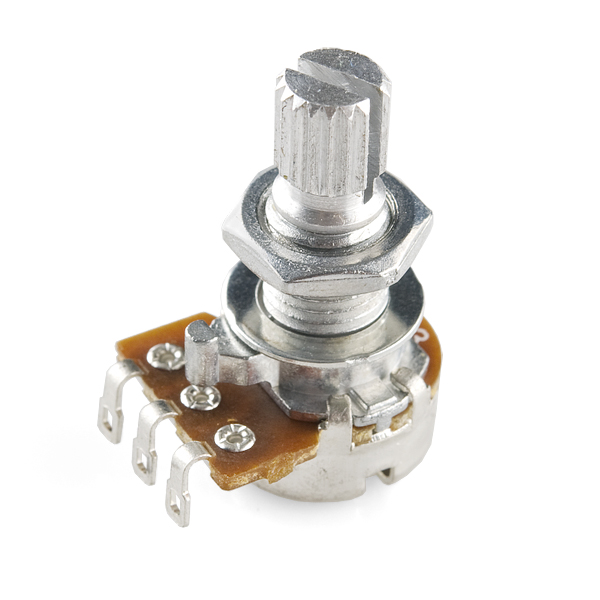
An adjustable potentiometer can open up many interesting user interfaces. Turn the pot and the resistance changes. Connect VCC to an outer pin, GND to the other, and the center pin will have a voltage that varies from 0 to VCC depending on the rotation of the pot. Hook the center pin to an ADC on a microcontroller and get a variable input from the user!
This pot has a 1/4" mounting diameter and has a 10K linear taper. Check the datasheet for dimensional drawings.
Rotary Potentiometer - 10k Ohm, Linear Product Help and Resources
Proto Pedal Example: Analog Equalizer Project
September 22, 2016
Building a gyrator-based analog equalizer using the Proto Pedal.
Proto Pedal Example: Programmable Digital Pedal
September 22, 2016
Building a pedal around the Teensy 3.2 and Teensy Audio shield. Changing the effect in the pedal is as easy as uploading a new sketch!
DIY Light Sculpture
August 23, 2018
In this digital fabrication project featuring 3D printing, laser cutting, and DIY electronics, you will build a beautiful design object for your desktop or night stand.
Core Skill: Soldering
This skill defines how difficult the soldering is on a particular product. It might be a couple simple solder joints, or require special reflow tools.
Skill Level: Noob - Some basic soldering is required, but it is limited to a just a few pins, basic through-hole soldering, and couple (if any) polarized components. A basic soldering iron is all you should need.
See all skill levels
Core Skill: DIY
Whether it's for assembling a kit, hacking an enclosure, or creating your own parts; the DIY skill is all about knowing how to use tools and the techniques associated with them.
Skill Level: Noob - Basic assembly is required. You may need to provide your own basic tools like a screwdriver, hammer or scissors. Power tools or custom parts are not required. Instructions will be included and easy to follow. Sewing may be required, but only with included patterns.
See all skill levels
Comments
Looking for answers to technical questions?
We welcome your comments and suggestions below. However, if you are looking for solutions to technical questions please see our Technical Assistance page.
Customer Reviews
3.7 out of 5
Based on 7 ratings:
1 of 1 found this helpful:
Perfect replacement pots or for use in new projects. Well built and small enough for cramped project boxes. Nice smooth operation and at a reasonable cost.
1 of 1 found this helpful:
Works Well
Bought this to use with the LM317 and made an adjustable bench supply from an old ATX PSU. Movement is smooth, mounts easily, and the matching silver knob looks awesome on it.
5 of 6 found this helpful:
Stated mounting diameter is off
I haven't tested it electronically yet, but just FYI for anybody out there drilling holes to mount these things, they won't actually fit in a 1/4" hole!! I found this out after drilling 1/4" holes through 1/4" acrylic. The posts wouldn't fit, and so, busting out my trusty micrometer, I measured the threads and, much to my surprise, the major diameter on the threads is actually around .265", not .250"!! This may not matter if you're going through 1/32"-1/16" material, but this makes a difference on thicker materials. I'd recommend an 17/64" or 9/32" drill for mounting holes.
Don't buy in bulk
Don't know if they test these before shipping, but out of the 16 I've tried so far from an order of 36, 1 is already a dud. Also don't buy in bulk -- they just throw them all in a single ziplock bag so a lot of the pins managed to get bent way out of shape during shipping. I mean it's easy enough to bend them back, but it's still uncool.
about what you'd expect
and a really nice consistent friction. Screw threads are adequate, nothing super high quality.
You can waste a LOT of time with these
I am a great fan of Sparkfun, and love their stuff - for my lab, an advantage over places like Digikey is that you don't have to wade through 100,000 exotic options to find a reasonable item for a regular shop. I also like cheap and easy. This is not the place for getting milspec parts for your next deep space probe. But. I have had a LOT of problems with these. The can be flakey, and flakey is the hardest thing to debug. Jameco has some slightly bigger ones for like $1.50 or so. Maybe I just got a bad batch, but I would avoid.
We designed a case to perfectly fit this potentiometer and you are welcome to use it in your projects :) Here's a link to the design files on thingiverse
Anyone know where I can get one of these but with a longer threaded portion. These are 7mm long so won't go through my wooden project box which is 1/4" thick. If I had a few more mm these would work.
Can somebody tell me where I can find these with audio tapers?
What is the power rating on these?
The datasheet says 0.04W. Unless it's a 'B', in which case it's 0.08W. Unfortunately it doesn't specify if they're referring to the taper, though that would be my assumption; and it's not a B taper. Either way, I'd stick with the lower of the two as a maximum rating.
what is the smallest amount of movement this can measure in degrees?
It's an analog device - technically, 'infinitely small'. The problem is that 1. the tolerance is all over the place, and 2. repeatability.. i.e. you actually trying to turn the knob 1 degree and the contact pin on the resistive track on the inside moving that same 1 degree every single time you do so. Whether or not this device is right for your purposes may be something you'll have to try out yourself. See also the 'How potentiometers work' link in the description. Edit: And my comment from 8 months earlier also has some tidbits along the same lines :)
How do I know what potentiometer to get? 10k ohm, 4.7k ohm?
That depends entirely on what you'd need it for, although if the intention is to use it with a microcontroller, either one will do as the exact Ohmage can be mapped to different values as needed once incorporated into a design where you can get an analog voltage read. Personally I prefer the 10k just because I know that halfway should be about 5k, quarter of the way 2.5k, etc. What's half way on a 4.7k? 2.35k? And a quarter? Brain's got better things to do than remedial math there :)
If you actually need one in an analog design, on the other hand, that design itself will dictate whether you'd want 10k, 4.7k, or something else entirely.
I'll reply just to this comment, can copy the conclusion to the other one when we get there.
Thanks for the help :)
What are the dimensions on the datasheet? I would like to build this in CAD, but the dimensions don't have any units. Anyone at Sparkfun, could you either tell us the units or roughly measure a physical potentiometer with calipers? That would be very helpful. Thanks, Sam
The dimensions are in mm as best as I can tell. L-15 mm, W- 7 mm, K- 7.5 mm, M-1 mm, T - 6 mm is what I measured on one from stock. Hope that helps!
The pixels - they have been vindicated \o/
As an aside, as one whose eyes are on the comments RSS frequently, I'd like to take this opportunity to say that you're doing an awesome job.
Hah, thanks! Same goes to you. We definitely appreciate how much you help out on the comments-makes our jobs easier :)
Disclaimer: I'm not at SparkFun (sadface).
From the datasheet, all the mounting diameters are 6. 6 'something'. Probably not 6 inches.
From the description: "This pot has a 1/4" mounting diameter". 1/4" is.. well it's a bit over 6mm but 1.4" will fit just dandy.
So let's assume the dimensions are mm.
That brings us to the next questions (asked a year ago, too, but I'll poke at them here).
Well there's only one row of pins, so the top-left one. Doesn't matter too much, though.
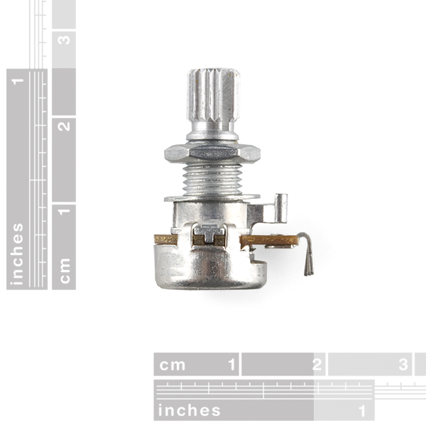
Well, thankfully SFE also tend to post pictures of the product next to a ruler, such as this one:
this pot next to a ruler From there we can measure other things. Let's go for a nice broad range, the 3cm mark. It comes down to about 364 pixels.
Now let's do a sanity check, the shaft mount is supposed to be 6mm, so would expect to measure (364px/30mm*6mm)~=73px across. I measure 75px. 2px would be ~0.16mm, so I'll take my chances with that.
mount shaft is 6mm diameter
We can determine the type next; the photos show us that the shaft mount has a slot all the way through, so it's a KQ type as indicated in the datasheet.
type is KQ
Let's tackle L next as we can narrow some others down down from there and is the longest measurement (least error!) L is measured from the end of the shaft all the way to the housing. Measuring that I get ~179px. Doing the math on that I get ~14.75mm. While not exactly 15, it's definitely not 20 or 25. This means that
L (full length of shaft) is 15mm (X = 2)
T (knob attach) is 6mm
M (neck) is 1mm
You'd think you could calculate W from here, but unfortunately the bevels of the neck are excluded. Still, if you take L - T - M = 8mm, it's unlikely that those bevels are 1.5mm broad if the neck itself is only 1mm, which means it should be 7mm. Can't hurt to verify by measuring pixels, though - about 85px gives just a few thousandth of a mm over 7mm.
W (mount shaft) is 7mm
Now, K can be 7.5mm or 6mm given our W of 7mm. 1.5mm isn't much, but it should be more than enough for measuring the pixels. Just about 91px gives, well, exactly 7.5mm.
K (distance from center of shaft to structural supports) is 7.5mm. (Y=1) H is a bit more difficult - do these come with pins bent (photo), or straight (datasheet)? Doesn't matter, we can still give it a go - some straight segments should be a reasonable approximation, so pixels along the board where things are still nice and straight is 126px, while the bent lead up until the solder eyes is about 3.6+2+3.2+4.2+6.7+13=32.7px, totaling about 158.7px or ~13.1mm. Unfortunately that's not 12.5mm or 14.5mm. It's closer to 12.5mm, so let's call it that - but only because if you're soldering it to a PCB, that lead length doesn't matter after you cut them off, and if you're mounting it to a panel and solder wires to it, you can bend the pins - just as in the pixture - should you need that 2mm of extra space in the housing.
H (center of shaft to solder eyes) is 12.5mm (Z=1)
Again though, I'm not at SparkFun and I don't have this part in hand. For all I know, the photo may be outdated (first comments from 3 years(!) ago) and they're now carrying a slightly different one, perhaps the one where K is 6mm :)
It doesn't look like it but are these bread board friendly?
Hello, Sadly no, this one is NOT breadboard friendly, That's what I'm here looking for today !!!!
I'm confused by the datasheet and have a couple of questions. First, can I freely turn the knob as many rotations as I want in any given direction? Second, if I can indeed rotate it however I wish, will it always give the same reading when pointed at the same angle? ie, will it always read X when pointed at 90 degrees, regardless of how many rotations I've put it through?
Should just be a single - incomplete - turn. The datasheet specifies it as 300° +/- 10°.
The remainder of your question thus technically doesn't apply - but just to run with it within the context of the above limitation: not the exact same value, but it should be pretty close. The main source of error would be in minute amounts of slack, and friction, that cause the slider to be positioned in an ever-so-slightly different position on the resistor 'track'. Because that track is relatively small, that translates to, percentage-wise, a fair bit of error. ( Note that this is unrelated to any error in one's ability to turn the shaft to the exact same position in the first place, and completely separate from the 'tolerance' specification. )
I also took a peek at the state of 'continuous' potentiometers and while they let you turn the shaft 'round and 'round, the vast majority of them have a resistor 'track' of about 340°. One of them specifies 352°. Note.. all of these cost more than $15 a piece because they're very specific instruments for very specific industrial processes.
It would be much cheaper - though more finicky - for you to take a potentiometer such as this one, take it apart, and remove the physical stops (assuming it is not a threaded shaft that ends up going up/down). You'd still be stuck with the 300° resistor track but at least you can turn it around freely.
Alternatively, depending on what you'd need this for, I'd look at rotary encoders.
I can't make heads nor tails of the datasheet. What units is it in? Which diagram on the top is the one for this product? What do Z and Y mean? :-/
Any update on reading the units? the datasheet is horribly non-descript. It is missing a lot of units for the measurements. I'm particularly interested in the position and diameter of the little peg that prevents it from spinning when panel mounted.
Does anyone know, do these rotate continuously?
300 degrees of rotation, +/- 10 degrees.
It's right on the top of the datasheet :P
Whoops, RTFM to me~ Thanks!
Is the shaft 1/4" for a 1/4" knob???
Sorry everyone. The descriptions are fixed. This one is linear. We also have a log.
Product title says linear, description says logarithmic.
Datasheet says the resistance taper is "A, B, C", whatever that means. :-P
I sure hope it's linear taper. Log taper is nice for audio, but for connecting to an ADC, linear makes a lot more sense.