- Home
- SparkFun I2C/SPI-to-UART Breakout - SC16IS750

SparkFun I2C/SPI-to-UART Breakout - SC16IS750
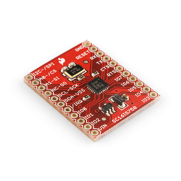
This is a breakout board for the SC16IS750, a handy chip used to convert I2C or SPI serial signals to a single-channel, high-performance UART. As an application example: we use this chip on our WiFly Shield to allow an Arduino to communicate with the WiFly RN-131G module - which is normally controlled via a UART - using an SPI interface. This allows for greater communication speeds and frees up the Arduino's UART for other purposes.
Power applied to the 'VIN' pin is sent through a 3.3V LDO regulator before powering the IC. The input pins of the SC16IS750 are 5.5V tolerant, so this board should work with both 3.3V and 5V controllers. Also populated on the board is a 14.7456MHz crystal, to serve as a clock input to the chip, and other supporting components.
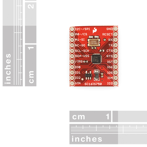
This board breaks out all pins of the SC16IS750 to two breadboard friendly 11-pin, 0.1" pitch headers.
Replaces:BOB-09745. The reason for the replacement is the 12.288MHz crystal on BOB-09745 did not allow for the full range of baud rates. The 14.7456MHz crystal on this board increases the functionality to include all of the common baud rates from 9600 up to 921600.
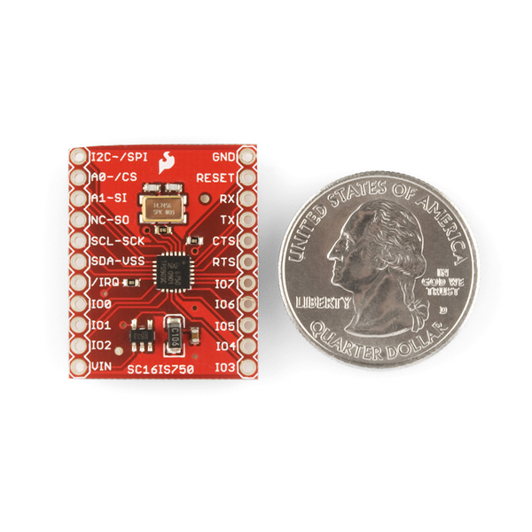
- 1.10x0.90" (27.9x22.9mm)
- Schematic
- SC16IS750 Datasheet
- GitHub
- For an example of how to use the SC16IS750, checkout the WiFly Library on the forum
SparkFun I2C/SPI-to-UART Breakout - SC16IS750 Product Help and Resources
Core Skill: Soldering
This skill defines how difficult the soldering is on a particular product. It might be a couple simple solder joints, or require special reflow tools.
Skill Level: Noob - Some basic soldering is required, but it is limited to a just a few pins, basic through-hole soldering, and couple (if any) polarized components. A basic soldering iron is all you should need.
See all skill levels
Core Skill: Programming
If a board needs code or communicates somehow, you're going to need to know how to program or interface with it. The programming skill is all about communication and code.
Skill Level: Competent - The toolchain for programming is a bit more complex and will examples may not be explicitly provided for you. You will be required to have a fundamental knowledge of programming and be required to provide your own code. You may need to modify existing libraries or code to work with your specific hardware. Sensor and hardware interfaces will be SPI or I2C.
See all skill levels
Comments
Looking for answers to technical questions?
We welcome your comments and suggestions below. However, if you are looking for solutions to technical questions please see our Technical Assistance page.
Customer Reviews
4.5 out of 5
Based on 4 ratings:
1 of 1 found this helpful:
Works great for prototyping
Breakout boards like these are great for proof of concept - either proving out a design before committing design to manufacture, or getting code up and ready for verifying quick-turn pcbs when they are ready.
Be aware that like many chips, these are only somewhat 5v tolerant. 5V SPI interfacing works just fine, but it's not completely clear that all of the IO pins can handle being driving at 5v.
Very handy breakout if you are short of UART/SPI pins
I am using a FEZ Raptor and I found the BOB-09981 overcame my problem. See blog at http://www.rescuerobot.org/drupal/?q=blog under "Homebrew Robot" for details about wiring and code.
A bit of an address issue with i2c
It was fairly straightforward to translate the spi code to i2c given that I already had the accelerometer running in i2c. But while the accelerometer has an address of 5C, this device has an address of 9A.. The breakthrough was reading an article that said i2c addressing is confusing. The 5C device worked fine but this device didn't work until I changed the address shift one bit to 4D. Then it worked. With shared devices on the i2c buss you can't do blocking IO so I had to do my reads by polling the device. But it worked fore reading my key presses and that is what I used it for.
I am using this with and Edison using C and mmra.
Is there going to be a replacement for this item? I was just about to order it only to find out it is retired
Sigh. There are more retired products I want to buy than ones actually for sale.
What is the manufacturer of the 14.7456Mhz crystal? I need the corresponding article number of the crystal and a datasheet. Many thanks!
Another one bites the dust. Since Sparfun retired the WiFly, I thought I cound rebuild it with the RN-131C breakout board and this one. As someone said before, there are more retired products I want to buy than ones actually for sale!
Is it possible to run this for UART to SPI? I have a sensor with high FRQ serial output and want to send the Data via SPI to the Arduino mini pro, as the serial of the mini pro is not fast enough.
I created a basic sketch to setup and test (using NewSoftSerial) this board with just an Arduino. Now you don't have to go wading through the WiFly library. Also, unlike the WiFly library, it uses the the native Arduino SPI code, so you'll need a new-ish version of the IDE. Enjoy!
SC16IS750_Test.zip
Dear friend do you have an example like that but using I2C interface? Thanks a lot
You should make this into a library unless there is one out there.
Sparkfun, on the next batch, will you fix the PCB? As stated earlier, there is no connection between \IRQ (interrupt pin) and the output header. The connection is present in the schematic, but missing in the PCB. This pin is essential to let the micro know when to read data without resorting to polling.
Other than that problem (I got around it using a jumper wire), this item is great for adding additional serial ports. In the near future I'll be releasing some code for Arduino using the I2C port.
Hi Rob,
How exactly did you solder the jumpwire? One end at the /IRQ pin I suppose and the other?
Sorry, I never actually got it to work. I thought I had soldered it correctly, connecting the jumper between the pull-up resistor and the /IRQ header, however upon further testing it was not connected properly. Further attempts to fix the jumper resulted in the destruction of the pcb trace connected to the /IRQ pin on the chip. Unfortunately I do not have the proper equipment to solder directly to the chip pins.
Hi There FYI I have one of these little magic BOB and needed to connect via I2C, not SPI I am using this library and it works : https://github.com/SandboxElectronics/UART_Bridge I added FIFOEnable(1); add the end of the begin function in SC16IS750.h to allow receiving strings (otherwise works with 1 character at a time) Hope this helps
The IRQ is not connected to the pin out because the signals have different names (/IRQ on IC1 and IRQ on JP4) I just soldered a wire between the right side of R2 to JP4/5 and it works fine.
Rob Reasons
Can somebody tell me what smd footprint the crystal has? 5032? Thanks
I've been trying to get this board to work without much luck. SI toggles just fine but SO remains high and I always readback 0xff from any register.
As a starting point, I just hooked up ground, 3v3 (on VIN), /SPI (to ground) and pulled SPI bus lines to my Aardvark SPI adapter and my Beagle I2C/SPI bus analyzer.
The SC16IS750 doesn't seem to be alive at all. I know it's not the analyzer/bus-master because if I short SI/SO the analyzer sees the data just fine.
Any hints ?
I've had similar problems with this board when trying to make it work with Raspberry PI, on SPI was getting 255 (0xFF) and on I2C was getting write errors. I2C problems got resolved after correcting the code - not all samples that I found online worked (specifically those trying software reset were problematic). SPI problem got resolved by setting 0x80 flag on register before read, while doing full-duplex transfer of 2 bytes - the last received byte is return value. That is, write buffer had to be (read_register | 0x80, 0), read buffer after transfer would be (not_important_discard, return_value). For SPI, there is no need to connect SDA-VSS to anywhere despite some information I found online.
Hi, I am having a similar issue, have you been able to solve this? What was the issue? Maybe it can give me some clues as to what my fault is. Thanks.
Would anyone happen to have a Raspberry Pi driver/example for this board?
So does this only work SPI/I2C > UART or does it also work as UART > SPI/I2C? I'd like to control an SPI LCD with a UART. Would this allow me to do that?
Unfortunately no. This thing is only an SPI slave, not a master, which would be required to work in reverse, unless by some weird chance your lcd can be a master.
does the input voltage have to be 5.5 or can i power it from 3.3 volts ?
There's another gotcha to this part. The data sheet well hides a crucial part of what you write to the subaddress register. See http://forum.sparkfun.com/viewtopic.php?f=14&t=25019
I'm trying to get this board working with the transparent terminal sketch
I've fixed the ocillator issue in the code 0x50->0c60 and I've tried with two boards -- one with the IRQ jumper and one without. In either case, the data gets garbled in transmission. There is a pattern to it. For example for an input of '1' I get 'g', 3->f, 5->e, 7->d, 9->c, a->O, c->N. I haven't found the pattern for even input values.
Anyone have ideas/suggestions?
inmcm's test program works fine. I only have problems wiring up to a UART on the PC. I've tried multiple PCs, cables, and terminal emulators. STUMPED!!!
OK. Found the problem. The TTL signals coming from the chip are inverted relative to my PC.
Just to help everyone out, this board works perfectly fine once a short jumper wire is soldered between the IRQ pin connected to the header JP4.5, and the /IRQ net on the chip side of the pull-up resistor R2. Just make sure that R2 is not disconnected from its pad when soldering on the jumper wire.
I agree the fix is easy... if you have a small enough wire, ironing tip and soldering skills.
What actually bugs me is that there was not a single reply from SparkFun on this issue... I would have probably been ok with a simply apology, though I think SF should offer a free replacement service for this board no matter where you bought it (directly or through a retailer). Simply ignoring the issue isn't what I consider "customer service".
If anyone was worried about being able to go below the 9600 baud floor mentioned above, don't be. With that crystal you should be able to go all the way down to about 4 baud (not quite DC, but pretty darn close). The spec sheet says we get a 16-bit divisor, with an optional divide-by-4 prescaler. It gives the formula:
divisor=(XTAL1 crystal input frequency/prescaler)/(desired baud rate * 16)
(14.7456E6/4)/(4*16) = 57600
I bought this at a reseller and didn't look here until I noticed the IRQ problem myself. It should have been easily spotted during QA that there is nothing going to that pin.
I think it's quite a big f-up... and of course now that I soldered break-away headers to the board I can't give it back :(
I can see the error with the IRQ in the schematic. On the chip the net connected to pin 11 is named /IRQ, however the net connected to pin 5 of the header is named IRQ. Eagle didn't connect the two pins because the nets are mislabeled.
can we use this product to read the data from the OS4000T compass in a I2C bus?
Sparkfun, In your Schematic you use the net name /IRQ on the chip side, but use IRQ on the header side. Please fix.
For others who need a work around, it looks like you can solder a jumper wire from the right hand side of the resistor to the /IRQ Pin.
to put it another way, as you look at the /IRQ header, solder to the resistor on the side between the resistor and the IC.
Are there any plans to modify the board to connect the /IRQ terminal on JP4 to IC1?
Just found out the hard way and here is a problem: There is no connection between JP4 pin 5 (IRQ) and pin 11 of IC1. Hope it help other.
Does anyone have any insight on how to write a Linux tty driver that interfaces to the SC1616IS750? I have a gumstix, and it would be great if I could talk to the UART as a tty device.
Thanks,
Paul
Can this chip do 31250 bps? I am planning an Arduino project that needs two independent MIDI interfaces; I know the ATMega1280 can do this but I'd rather stick with the good ol' 328.
For some of the beginners on this technology, please refer to the following link on details on the I2C (or IIC) - this link gives a fairly good description on what-is-it and how-can-you-work-with-it.
http://www.i2c-bus.org/
Cheers
The datasheet appears to be a copy of the schematic. Copyover problem?
yep, fixed