- Home
- Product Categories
- Kits
- Multimeter Kit

Multimeter Kit
Replacement:KIT-10956. We've made some minor changes to this kit to make it easier to assemble. This page is for reference only.
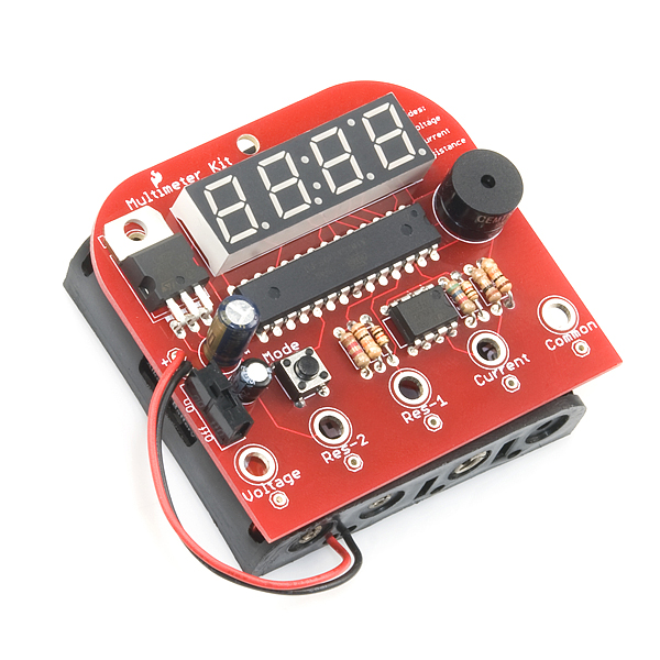
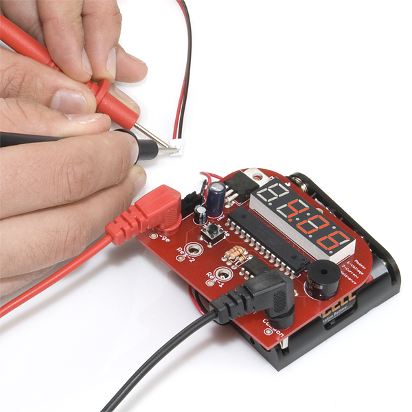
The Multimeter Kit provides you with everything you need to make your own multimeter capable of measuring voltage (0-30VDC, 0.05 resolution) current (0-500mA, 1mA resolution) and resistance (0-100kΩ). The resistance mode also includes a continuity test: the buzzer will sound when the resistance probes are shorted together, this is one of the more handy tools of any multimeter.
Using the Multimeter Kit is very straightforward. To measure voltage connect your probes to the 'Voltage' and 'Common' pins, for current measurement the 'Current' and 'Common' pins. Resistance measurement uses the 'Res-1' and 'Res-2' pins. The decimal points are used in resistance measurement mode to indicate 10kΩ and 100kΩ ranges.
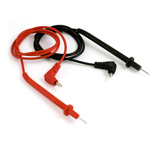
This kit now includes test probe cables! Batteries, however, are not included.
Please note: using the resistance measurement mode on live circuits is not recommended. Also, do not test current or voltage on devices that may be outside the measuring range (no negative voltages or currents)! The multimeter is very simple, and won't replace your Fluke meter, but it works perfectly for simple troubleshooting.
Be sure to read our How to Use a Multimeter tutorial to find out how to properly use a meter (as if there was a standard way!).
Replaces:KIT-09573
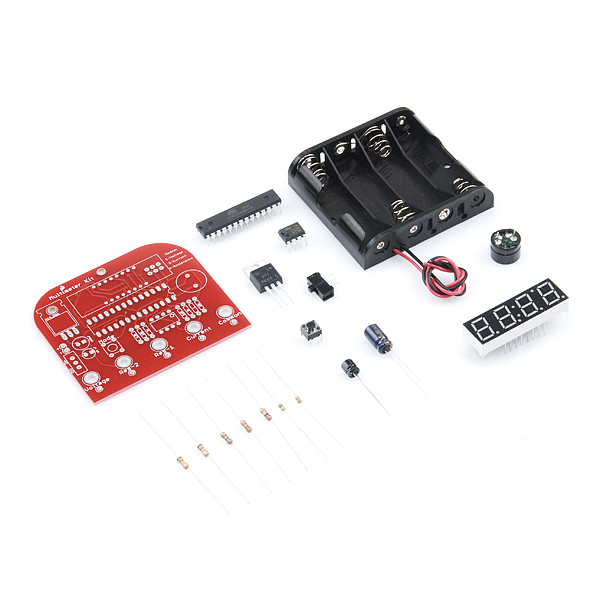
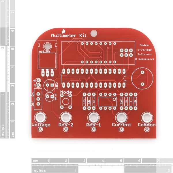
- 1x Multimeter Kit PCB
- 1x ATMega328 programmed for Multimeter Kit
- 1x LM358 Op-Amp
- 1x 3.3V Voltage Regulator
- 1x Red 4-Digit 7-Segment Display
- 1x Buzzer 2.048 KHz
- 1x Battery Holder Pack AA x 4
- 1x 100uF Capacitor
- 1x 10uF Capaciator
- 2x 1.0kΩ Resistor
- 2x 10kΩ Resistor
- 1x 5.6kΩ Resistor
- 1x 1.2kΩ Resistor
- 1x 1.0Ω Resistor
- 1x SPDT Mini Power Switch
- 1x Push Button Switch
- 1x Banana to Test Probes Pair
Multimeter Kit Product Help and Resources
How to Use a Multimeter
January 9, 2015
Learn the basics of using a multimeter to measure continuity, voltage, resistance and current.
Comments
Looking for answers to technical questions?
We welcome your comments and suggestions below. However, if you are looking for solutions to technical questions please see our Technical Assistance page.
Customer Reviews
No reviews yet.
There is an error in the code for voltage mode. The calculation gives you the voltage at the AD input and NOT the voltage at the probe. The calculation should multiply by 3.281*1.12/1.2=3.062. That would fix the error reported by bdodds. The claculation does not factor in the voltage divider (which needs to be scaled by 10X due to the decimal point.
works quite well for troubleshooting purposes. Although, would be good if we could calibrate it.
Couple of Qs.
How long does this stay on? IE: A few minutes to indefinitely ?
Can I mess with the input/calibration so I can turn this into my output of a home-built Anemometer
Thanks for any input given :)
put it back in stock plz i need it
When is it gonna be back in stock? I need for my science project due next week! Can you make just one and send that to me?
I wish there was a header on this to connect a usb to rs232 connector. FTDI whatever. I would like to have this communciate with my PC...
I just build this circuit from extra SparkFun parts I happen to have laying around. :)
I had enough parts to get the Voltage mode working, but have a few questions.
How do I tweak the accuracy? I have a bench power Supply set to 12v that reads 12v on all my other DMM, but this one reads 12.78. Would this be a code tweak or a resistor tweak?
If I changed the Voltage mode bit of code from 3.281 to 5.000 could I run this on a 5V source instead of 3.3?
I'm looking at the pictures and I see the probes plugged into banana jacks, but I don't see these jacks on the parts list or in the discrete parts picture. Are they included in the kit?
It looks like the holes in the PCB are sized so that banana plugs fit right into them, so no additional banana jack hardware is needed. A clever idea, but not so good when comes to durability.
Remember that this is more of a concept demonstration kit than a real multimeter; it has very little input protection and a measurement accuracy in the neighborhood of +/-10%.
Furthermore, it has an input impedance hovering in the kOhm range, so although it's sort of cute, I suppose, it's not a usable multimeter in any respect.
As an example, if you used this kit to measure the voltage across a simple voltage divider made with some 10k resistors, you would not get an accurate result -- this kit would load down your circuit too much.
Nice little kit. One thing puzzles me about the schematic though - the LEDs are connected directly to the AVR pins. The AVR runs 3v3 and the LED Vf is 2v1. There are no current limiting resistors. Having looked at the source code each digit is turned on for 1ms in turn during the interrupt routine. I presume you're relying on the AVR's current limiting to stop the segments getting more than their 20mA Ifmax? Not sure how that's going to do the AVR in terms of reliability as I'm not sure it's rated to take that sort of punishment continuously? Or have I missed that bit of the AVR data sheet? :))
In any event though, absolutely love the simplicity of this design. That's what electronics should be about - minimum parts, maximum elegance!
Datasheet says the AVR is good for up to 40mA per pin. Also, displaying only one character at a time means that each pin (character) has a duty cycle of no more than 1/4. So even if it does load it more than specified, it's only for a very short period.
That said, I would recommend re-programming it unless you were sure it was getting a short duty cycle.