- Home
- Product Categories
- Buttons and Switches
- Rotary Encoder LED Ring Breakout Board - Blue

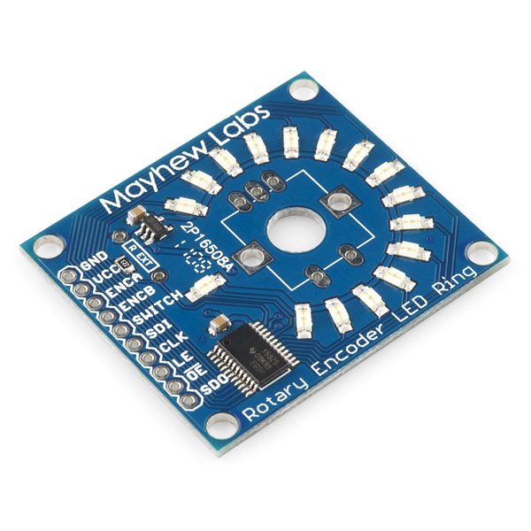
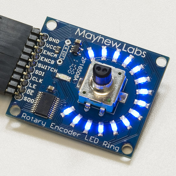
Rotary Encoder LED Ring Breakout Board - Blue
The Rotary Encoder LED Ring is a position indicator for rotary encoders. Traditional knobs with indicator lines do not give accurate representation of an encoder’s value since rotary encoders have no start or end point. The Rotary Encoder LED Ring has through-hole or shaft mounting for most standard encoders and uses a Texas Instruments TLC5925 shift register to interface 16 blue LEDs to any microcontroller through SPI. A microcontroller can be programmed to output any desired sequence on the LEDs.
Rotary Encoder LED Ring Breakout Board - Blue Product Help and Resources
Core Skill: Soldering
This skill defines how difficult the soldering is on a particular product. It might be a couple simple solder joints, or require special reflow tools.
Skill Level: Rookie - The number of pins increases, and you will have to determine polarity of components and some of the components might be a bit trickier or close together. You might need solder wick or flux.
See all skill levels
Core Skill: Programming
If a board needs code or communicates somehow, you're going to need to know how to program or interface with it. The programming skill is all about communication and code.
Skill Level: Competent - The toolchain for programming is a bit more complex and will examples may not be explicitly provided for you. You will be required to have a fundamental knowledge of programming and be required to provide your own code. You may need to modify existing libraries or code to work with your specific hardware. Sensor and hardware interfaces will be SPI or I2C.
See all skill levels
Core Skill: Electrical Prototyping
If it requires power, you need to know how much, what all the pins do, and how to hook it up. You may need to reference datasheets, schematics, and know the ins and outs of electronics.
Skill Level: Competent - You will be required to reference a datasheet or schematic to know how to use a component. Your knowledge of a datasheet will only require basic features like power requirements, pinouts, or communications type. Also, you may need a power supply that?s greater than 12V or more than 1A worth of current.
See all skill levels
Comments
Looking for answers to technical questions?
We welcome your comments and suggestions below. However, if you are looking for solutions to technical questions please see our Technical Assistance page.
Customer Reviews
No reviews yet.
Hey everyone!
I was lucky enough to be one of the few to beta test these for Mayhew Labs. Let me first say that while the idea is simple, the execution is amazing!
I've put together a few videos of the rings in action which you can check out below:
Ring used as a MIDI VU meter from Traktor
Ring used a encoder feedback indicator
3 Rings daisy chained together with a flashy demo
At first look everything is awesome ... except we're looking at examples that aren't coded for real end-usability. EX: - The # of clicks to activate each LED step is inconsistent - The click function on the encoder doesn't toggle the LED on/off
If we're looking to use this for real feedback: - 1-encoder-rotate-click >> 1 LED increase / decrease - encoder-rotate-click >> at least increments LEDs at consistent click-intervals - encoder-press >> toggles an on off
Ok so scaling the encoder value to give a single LED per encoder-click-rotation:
Figure out the top / bottom end of your encoder values
Get the interval output from your encoder by looking at the count between clicks in the above sketch
Divide total steps by # of LEDs
number of LEDs ( 16 in this encoder LED ring ) * above number
Scale the input to tmpvalue ln:97 by the interval output of your encoder
Edit the scaledCounter value on ln:104 ( EX: scaledCounter = map(counter,0,255,0,15); )
upload
Enjoy
NickVD,
Awesome videos/examples on the Rotary Encoder LED Ring Breakout Board. I just ordered one and I'm excited about its arrival. I would really appreciate it if you could send me a link for the rotary switch you used in your "Ring used a encoder feedback indictor". It looks like it's a nice, clicky, 15 position rotary switch with a push button, which I'm having trouble finding.
--Robert
Given the date of introduction, at first glance I thought this was an Arc Reactor board. +1 for being a real product that I can order and play with!
Does anyone know where (what country) these are manufactured in? Thank you!
I put together a video review here: http://vimeo.com/63987653
I think it's a great piece of gear, but I was quite underwhelmed with the lack of any kind of glitch filtering network on the encoder outputs.
In the demo video it is shown that you can mount the rotary encoder through the board from the back. This would be preferable for my project as I would like to have the LEDs as close the the enclosure as possible. Is there an easy way to solder the rotary encoder to the board if it is installed this way? Or would I just have to solder some wires to the pins and then to the breakout board?
On our encoders, it looks like you could bend the legs 180 degrees and mount it from the back, but personally I'd be wary of this since you could easily snap a leg off. The safest thing might be to not bend the legs, and solder some bare wire (think clipped resistor leads) from the header holes down to the legs.
I have a demo and some code that shows how to drive the LEDs from a Raspberry Pi. Hope someone finds it useful.
here is my project using 4 of these in Traktor as well! Arduino MIDI Rotary Encoders
great looking product but, there is little to no examples of how to code it. wasted my money on something I can't use.
Don't worry Midknight5000, you didn't waste your money! I'll explain how the example code works a little and then explain how you can output to the LEDs anything you would like.
In the example there is an array of 16 bit values that represent the on/off state of 16 LEDs (0x0 means all LEDs off, 0x2 means just the second LED on...). The rotary encoder counter indexes this array of 16 bit values. So looking at the first array, if the encoder has been rotated 3 counts, the LED output would be 0x4 (only the 3rd LED would be on). There is a scaling that happens to show how you can make the output change every 10 turns instead of 1, for example. This is not really needed for functionality.
Now the output actually occurs (and this is where you are most interested) in these lines: shiftOut(SDI,CLK,MSBFIRST,(sequence[sequenceNumber][scaledCounter] >> 8)); shiftOut(SDI,CLK,MSBFIRST,sequence[sequenceNumber][scaledCounter]);
Since there are 16 LEDs, we have to send two 8 bit sequences. We bit shift the high 8 bits and send them, then we send the lower 8 bits next. I think we need an an example:
Suppose you want every 3rd LED on. This is 0b1001001001001001 (binary) = 0x9249 (hex) as seen in OSX or Windows programming calculator. 0x9249 >> 8 (shift the bits right 8 times) gives us the upper 8 LED on/off states, ie : 0b10010010 = 0x92. This is sent to the LED Ring. Then, the remaining 8 LED states are sent. We use a 16 bit value, but since the Arduino is 8 bit, the upper 8 bits (which we already sent) are disregarded. 0b01001001=0x49 is sent.
So here is the easiest way to send anything you'd like: unsigned int myLED = 0xDB6D; //1101101101101101, 1 means LED on, 0 means LED off digitalWrite(LE,LOW); //let the LED Ring know you are talking to it shiftOut(SDI,CLK,MSBFIRST,(myLED >> 8)); shiftOut(SDI,CLK,MSBFIRST,myLED); digitalWrite(LE,HIGH); //let the LED Ring know you are done
There is another approach that includes bitwise OR'ing that has the benefit of being able to turn on/off any single LED, regardless of the state of other LEDs. It might be better for applications that don't output a set sequence. I can show if anyone is interested.
Thanks! I a newbie so shift registers confuse me but you have made it easy to understand. I'm going to try it asap.
I am a newbie to Arduino programing and am am attempting to run the ledRing demo examples generated by NickVD. I have no problem running the Arduino Example Code from the link on this site but I cannot run the ledRing demo examples. I have downloaded and installed the ledRings folder as recommended by NickVD into my /Arduino/libraries folder. No problem opening the example files but everyone of them gives the same error when compiling. Error message :"ledRings" does not name a type. I am running Arduino 1.0 on a mac, hardware is an Uno. I have even tried moving the ledRings.h and .cpp file into the same folder as the example demo file I am trying to run such that the sketch window shows the demo code and has tabs for the library files. Obviously I am doing something wrong. Help?
sybednar,
I think this may have to do with the version of Arduino software. The path Nick gives may be the old library path. The current software looks for libraries inside your sketchbook folder and you add a library within a drop down menu. See if either of these pages set you up:
http://arduino.cc/it/Reference/Libraries
http://arduino.cc/en/Guide/Environment
If not, you may need to look at your settings file (use caution if you do): http://arduino.cc/hu/Hacking/Preferences
How do i code this to just turn all the light on, without a switch hooked up to it?
Hom many pins does this take from Arduino? Why doesn't this just work using I2C or Serial interface?
I received my Rotary Encoder LED Ring breakout board. I had it soldered, wired up to my Arduino Duemilanova, and functioning with the example code in minutes. Very cool! Looks fabulous. I love it.
I have one big problem though. When I hook it up to my Arduino Mega, which is what I need it on, using the exact same sketch and the exact same pins, it does not work. The button press LED comes on (the one below the knob), but the the rest of the ring never comes on. I've checked everything very carefully, but I can't figure out why it works repeatedly and consistently on the Duemilanova but it doesn't work on the Mega. It doesn't seem like there would be any significant difference between these two Arduino boards that would effect the breakout board.
Does anyone have any clues for how to resolve my problem?
I can think of two things to check. First, check the pin names you are using in your code. The same pins may have different names on the Mega than on the Duemilanova. Second, the code that reads the rotary encoder needs to know what port the encoder is on:
#define ENC_PORT PINB
The port names may be different on the Mega than the Duemilanova.
This is exactly what I am looking for. The only thing missing is a Eagle library file with the unit as a device, i.e. outline on the brd, hole locations, pin assignments in the schematic, etc. Even something as simple as a outline of the device showing relative hole and pin locations + hole sizes would be great.
Is it possible to use this just as a visual device? In other words I just want see the leds light as the encoder is turned. Just the board,encoder, and power. No microcontroler.
Short answer: No.
How do you propose to make the lights correspond to the encoder output without the microcontroller? If you want this as just a visual device, just just the default firmware and don't connect the microcontroller up to anything else.
Kudos to SFE for releasing a real product today!