- Home
- Product Categories
- Kits
- Colorganic Spectralizer Kit


Colorganic Spectralizer Kit
Replacement: None. We are no longer carrying this spectralizer kit in our catalog. This page is for reference only.
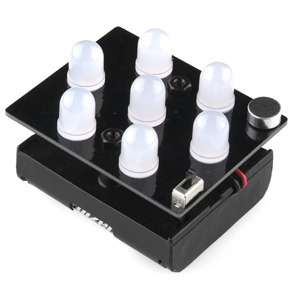
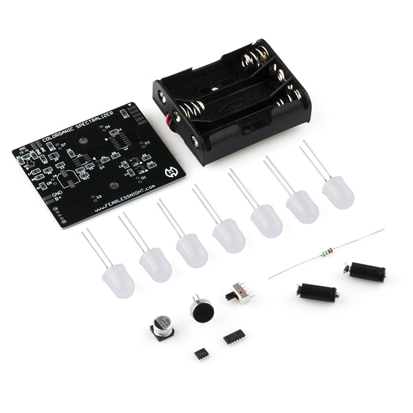
The Colorganic Spectralizer is an audio spectrum analyzer with seven bright 10mm colored LEDs. Use it as a miniature color organ or just a flashy desktop display thing. Each LED responds with a brightness that's in proportion to the sound level at a particular frequency. The Colorganic Spectralizer comes complete with an integrated microphone and runs for hundreds of hours on one set of AA batteries.
This kit is an advanced level electronics construction project because it requires soldering skills with surface mount technology parts, so it is not recommended for beginners. You will need patience and a fine touch to assemble this kit successfully. You might want to check out our SMD soldering tutorial.
The indicator LEDs can be arranged in any color layout that you want. You can use the standard layout, or rearrange the LED colors to any design that you desire. In order to assist you with the color layout design, use the color layout designer tool before assembling the kit.
Comments
Looking for answers to technical questions?
We welcome your comments and suggestions below. However, if you are looking for solutions to technical questions please see our Technical Assistance page.
Customer Reviews
No reviews yet.
Just build this. This is a GREAT SMD PROJECT. Specially for people that have MUSIC, ELECTRONICS and HACKING as a hobby.
On the side note... What ever you do don't use your solder sucker on smd resistors
Just finished my kit as part of an Advanced Skills Soldering class at my local hacker/maker space ( http://nova-labs.org/wiki/education/advanced-skills-soldering ). Happy to say mine works although I think the mic could use more amplification.
First - Thanks Fearlessnight! Lot of fun and great first smd project. There's not many and the layout and resist make it super easy.
I fixed a weird a problem...if anyone is seening the same thing here's what I did.
Initially, tested LED orientation, continuity, R values per circuit.
And while it worked at 3v - off an adj power support - worked perfectly. It didn't at 4.5-5v. Two LEDs stayed "stuck" on until there was a large sudden noise (like a clap), two other LEDs mostly always flickered...back to 3v and it worked great again.
I still don't know the exact problem, but I decided to remove and test and resolder R5,6 since they set the voltage midpoint and maybe there was a teeny bridge which made a difference at higher voltages? And while I still get the same readings as before now it works fabulously.
i just finished making this kit(my first time at SMD). altough i accidentally ruined the 20k resistor on my first try, everything else went smoothly. i love the spectralizer itself and i actually had fun in soldering SMD components.
i hope sparkfun will carry more SMD kits in the future.
I noticed a peculiar thing: in the instructions and schematics U1,U2A are different chips, but in my kit I have the exact same two 5 pin chips from the "U1,U2A" holder of the kit which on the kit states is the MCP6L91R, verified with lights and a magnifying glass.
Is the schematic/assembly instructions an outdated example?
Don't do what I did! Read the instructions before working! Turns out this issue is mentioned and shown in the very next page on the instructions, hah! They ARE correctly the same chip.
Sorry about the confusion; the initial batch of these kits used different opamp chips. The newer kits use all the same opamp chip to make the kit easier to build. If you get one of the earlier kits (PCB #1212), you have to make sure not to mix up the opamp chips. In the newer kit (PCB #110222) all you have to do is install the chips at U1 and U2A without worrying about mixing them up.
I built the kit and feel like I am so close to getting it working. Does anyone else have the issue of the ALL of the LEDS being ON all of the time? I tried to see if it was just to sensitive but they are all at maximum brightness so it is hard to tell.
If anyone knows how to fix the problem of all of the LEDS being constantly on, please tell me! Thanks.
don't know if the problem still bothers you, but the manual says that if the leds are on continuously then they may be soldered backwards.
check the polarity. the leds long lead(positive) goes into the square hole.
My Colorganic Spectralizer requires crazy loud volumes to excite the LEDs. Way louder than your "new product thursday video" would suggest.
I did as the troubleshooting guide suggested: To permanently increase the microphone sensitivity, replace R9 with a higher value resistor."
I had no resistor in slot R9 so i cut the trace and added a potentiometer instead. This only seems to turn the sensitivity down further thereby exacerbating the problems.
Any help would be great. I need this to work before I can write it up, teach it, hack it and gift it.
Thanks,
Matt
http://crashspace.org
Ok, I've not really had much change in things performance... yet.
The support I've received from Rich over at Fearless Night has been amazing. He has suggested several possible issues and explained with great depth how I might diagnose the problem.
I've learned a lot more about this kit than I would have otherwise and felt confident enough to order a second knowing I'll get em both working in short order.
Great work, sparkfun! Working with these has been a real joy.
thanks, matt
I got this working like a champ! It is super sensitive. I've taken to learning about the microphone circuit and adding a switch with additional resistors so I can turn down the sensitivity for nightclub settings
It turned out i had a few suspect solder joints. I noticed while attempting to test the microphone as Fearless Night suggested. The real trick was getting a high powered light and magnifying glass and really be sure everything was soldered nicely. The opamp on the mic was definitely not down properly. The easy thing there was to flux it grossly then let a little heat reflow it into place.
This is a great kit and for my second attempt at SMD it is about as fool proof as it gets.
thanks again for the continued support, Fearless Night!
-=matt
WANT! WANT! WANT! WANT!
Too bad I just ordered yesterday....
I guess I'll have to wait until at least next week.
Cool, someone still uses assembly language.
While I haven't played with this board specifically, I have rigged together a MSGEQ7 with the microphone as described and noticed that it is often useful to have a variable resistor to set the threshold for triggering the output (e.g. an LED). Maybe in version 2.0?
We found the kit pretty useful and sensitive for its purpose. Of course you could adjust it for other applications, but it really works well for what we were using it for :-)